AMD Geode™ LX Processors Data Book 465
Video Input Port
33234H
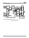
6.9.3 Functional Description
The Video Input Port (VIP) receives 8- or 16-bit video or
ancillary data, 8-bit message data, or 8-bit raw video, and
passes it to data buffers located in system memory. The
primary operational mode is as a compliant VIP 2.0 slave.
The VIP 2.0 specification defines the protocol for receiving
video, VBI, and ancillary data. The addition of the Message
Passing and Data Streaming modes provide flexibility in
receiving non-VIP 2.0 compliant data streams. The VIP is
essentially a DMA engine. Input data is packed into
QWORDs, buffered into a FIFO, and sent to system mem-
ory over the GLIU. The VIP masters the internal GLIU and
transfers the data from the FIFO to system memory. The
maximum input data rate (8 or 16 bits) is 150 MHz. The
GLBus (64 bits) operates from 200-400 MHz correspond-
ing to the DDR clock rate to external memory.
The VIP can successfully input line sizes as small as 12
clocks with 20 clocks of blanking, with a 16-bit data/100
MHz VIP clock rate at 400 MHz GLIU, when the VIP's prior-
ity is equal to that of the DC. The limitation has to do with
the total line length (active data + blanking time). Any size
of active data can be received if a reasonable amount of
blanking is provided. The above case corresponds to a 6-
pixel line. This is likely smaller then anything that realisti-
cally will be received (and at a higher frequency then the 75
MHz max). The VIP line size limitation is determined by the
input frequency and the GLIU latency. The worst case is
with a high frequency VIP clock and low frequency GLIU
clock in a busy system. The VIP FIFO Line Wrap Interrupt
(INT) is generated if the line is not received correctly. If this
INT occurs, VIP priority should be increased and/or the
blanking time of the input line increased. As there is no
specification/requirement regarding VIP minimum line size,
it is recommended that any non-standard input have ~100
clocks of blanking. This prevents any special priority
requirements for “postage stamp” size frames.
6.9.4 VIP Operation Modes
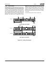
The VIP provides direct hardware compatibility with the
VESA 2.0 Standard (VIP 2.0), Level II. VIP 2.0 data is a
simplified BT.656 video format. The simplification is due to
VIP only having to receive data. (VIP does not concern
itself with specific frame timing) The data the VIP receives
is only stored in system memory. In addition to receiving
BT.656 video format data, the VIP can also receive 8-bit
message data and 8-bit streaming data, allowing the
AMD Geode CS5536 companion device connected to the
VIP to load data directly into the AMD Geode LX proces-
sor’s system memory. The Message Passing and Data
Streaming modes are not defined in the VESA 2.0 specifi-
cation. The VIPSYNC output provides a software controlled
output that can be used for frame/data synchronization with
output devices that support data throttling. VIP must be
configured to receive specific data types. The following
input modes are supported by the VIP.
• Mode 1a - VIP 1.1 compatible mode (BT.656 data with
following notes):
— Task bit is used to indicate VBI data within the video
stream (T = 0 for VBI Data, T = 1 for active video).
— Video data is stored in the Task A video base
address. VBI data is saved in the Task A VBI base
address.
— Video Flags T, F, and V can only be changed in the
EAV code.
— During vertical blanking there must be a minimum of
one SAV/EAV scan line.
— 8-bit data only (EAV/SAV packets + ancillary data
packets).
• Mode 1b - 8-bit VIP 2.0 Level I mode (BT.656 data with
following notes):
— Video Flags T, F, and V are valid in the EAV and SAV
code, valid values must appear no later then the SAV
of the first scan line of the next active region.
— Task bit differentiates between two video streams.
These streams can be interleaved at a scan or field
rate.
— V bit differentiates between active video and VBI data
(V = 1 for VBI data, V = 0 for active video).
— During vertical blanking there must be a minimum of
one SAV/EAV scan line.
— New Video Flags - The P Nibble is redefined as
[NON_INT,REPEAT,Reserved,EXT_FLAG].
— 8-bit data only (EAV/SAV packets + ancillary data
packets).
• Mode 1c - 16-bit VIP 2.0 Level II mode (BT.656 data with
following notes):
— Video Flags T, F, and V are valid in the EAV and SAV
code, valid values must appear no later then the SAV
of the first scan line of the next active region.
— Task bit differentiates between two video streams.
These streams can be interleaved at a scan or field
rate.
— V bit differentiates between active video and VBI data
(V = 1 for VBI data, V = 0 for active video).
— During vertical blanking there must be a minimum of
one SAV/EAV scan line.
— New Video Flags - The P Nibble is redefined as
[NON_INT,REPEAT,Reserved,EXT_FLAG].
— 16-bit data only (EAV/SAV packets + ancillary data
packets).
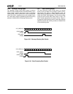
• Mode 2 - Message Passing mode (8-bit):
— vip_vdata[8] = start_msg, vip_vdata[9] = end_msg.
— 8-bit data only.
• Mode 3 - Data Streaming mode (8-bit):
— vip_data[8] = start_msg, vip_vdata[9] =
vip_data_enable.
— 8-bit data only.
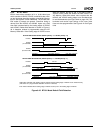
• Mode 4 - BT.601 mode (8/16-bit):
— No SAV/EAV recognition. Input timing based on
VSYNC and HSYNC inputs.
— HSYNC input on pin LDEMOD, VSYNC input on pin
VDDEN.
— TFT output mode cannot be used when VIP is config-
ured in BT.601 mode.


