464 AMD Geode™ LX Processors Data Book
Video Input Port
33234H
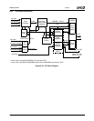
6.9.2.1 Input Formatter
The Input Formatter receives 8- or 16-bit VIP input data, It
does a 4:2:2 to 4:2:0 translation (if enabled) and formats it
into either linear data or planar data for storage in the Cap-
ture RAM.
6.9.2.2 Input Control
The Input Control block operates in either VIP 2.0 16-bit
mode, VIP 2.0 8-bit mode, VIP 1.1 compatible mode, Mes-
sage Passing mode, Data Streaming mode, or BT.601
Input mode. The Input Control block decodes preamble
and status from EAV/SAV and ancillary packets as well as
start/stop control for message passing packets or HSYNC/
VSYNC timing in BT.601 like input mode and generates
control to the Input Formatter and Capture RAM. Video
frame timing is decoded and passed on to the Address
Generator and GLIU. The VIP input state machine is imple-
mented in the Input Control block.
It should be noted that values from the configuration and
control registers are synchronized to the video clock before
being used by the Input Control block.
The VIP Input Control block contains:
• A state machine that keeps track of the video stream
protocol.
• Logic to infer the odd/even VBI/ancillary packet informa-
tion necessary to store data in memory.
• Sequencing control generation for the Input Formatter.
• Generation of start and stop capture, as well as capture
active status.
• Line start and end logic.
6.9.2.3 VIP Capture RAM
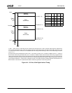
The Capture FIFO is a 256 WORDx64bit dual port RAM.
The input side is driven by the VIP clock. The output side is
driven by the GLIU clock. The memory is divided into a 192
QWORD buffer for video and a 64 QWORD buffer for ancil-
lary data when linear buffers are defined in system mem-
ory. It is partitioned into four 64 QWORD buffers when
planar buffers are defined in system memory. One 64
QWORD buffer is used for each of the Y, U, V and ancillary
data types. Data is stored in QWORDs. The watermark at
which the FIFO begins emptying is programmable. Gener-
ally, a minimum of eight QWORDs are stored in a buffer
before GLIU write. This enables two consecutive burst write
requests to be issued, which should provide the most effi-
cient cycle times to system memory. Programmable thresh-
old level flags are available to monitor data levels. This
should be helpful in debugging. Memory BIST is imple-
mented and can be invoked from the JTAG logic from a
MSRs. The memory can also be read/written using VIP
memory mapped registers.
6.9.2.4 VIP Register Block
The VIP register block contains the Address Generator,
MSR registers and memory mapped registers.
The Address Generator supports up to four data streams
(Y, Cr, Cb, and ancillary). Each data stream has an inde-
pendent logical FIFO. The Capture RAM is partitioned into
four FIFOS for planar storage mode (Y, Cr, Cb, and ancil-
lary) each being 64 QWORDs deep. In linear storage mode
the Capture RAM is partitioned into two FIFOs (Y = 192
QWORDs, ancillary = 64 QWORDs). Four vip_output_addr
blocks provide individual FIFO management and the VIP
Output Control block controls the time-slicing of GLIU
request for each FIFO. A separate buffer (system memory
address) is maintained for each data type as described by
Table 6-74 on page 475. The video base addresses regis-
ters are double buffered so address updates can be made
for the next frame while the current frame is being pro-
cessed.
The memory mapped registers are contained in the VIP
register block. Interrupt generation, and logic for updating
the base registers at frame boundaries is also implemented
in this block.
6.9.2.5 GLIU Interface
The GLIU provides a standard interface to the AMD Geode
LX processor. The VIP is both a write master and a slave
on this bus.
As a write master, the VIP performs write requests to send
single beat writes, or a burst of four QWORDs to memory.
The VIP is considered a low-bandwidth isochronous mas-
ter to the GLIU. A FIFO watermark threshold is program-
mable, which allows the write transaction priority to be
increased when the data count in the FIFO exceeds the
threshold. Handshaking exists between the GLIU master
and the Output Control/Address Generation blocks so that
address and data is supplied at the correct cycles.
As a slave, the VIP stores register data from the GLIU and
returns register data being read by the GLIU. Bursts are not
supported by the slave interface. Both MSRs and memory
mapped registers are accessible through the slave inter-
face. The front end control generates the per-byte write
enables to all registers except the base registers.


