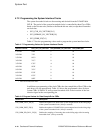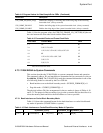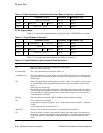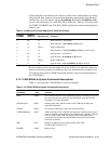
4–26 Cache and External Interfaces
21264/EV68A Hardware Reference Manual
System Port
•
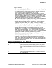
There is no mechanism for the system to reject a 21264/EV68A-to-system com-
mand. ProbeResponse, VDBFlushReq, NOP, NZNOP, and RdBlkxSpec (with a
clear RV bit) commands do not require a response from the system. Systems must
provide adequate resources for responses to all probes sent to the 21264/EV68A.
• Systems that program the Cbox CSR BC_RDVICTIM[0] to immediately follow
victim write transactions with read transactions and allocate combined resources
for the pair, may find it useful to increment the SYSBUS_ACK_LIMIT[4:0]
counter only once for the pair. These systems may assert Cbox CSR
RDVIC_ACK_INHIBIT, which does not increment the
SYSBUS_ACK_LIMIT[4:0] count for RdBlkVic, RdBlkModVic, and RdBlkVicI
commands.
• Systems that maintain victim data buffers may find it useful to limit the number of
outstanding WrVictimBlk commands. This can be accomplished by using the Cbox
CSR SYSBUS_VIC_LIMIT[2:0]. When the number of outstanding WrVictim
commands or CleanVictim commands reaches this programmed limit, the Cbox
stops generating victim commands on the system port. Because victim and read
commands are atomic when BC_RDVICTIM[0] = 1, the RdBlkxVic commands are
stalled when the victim limit is reached. Programming the
SYSBUS_VIC_LIMIT[2:0] to zero disables this limit.
4.7.7 System-to-21264/EV68A Commands
The system can send either probes (4-cycle) or data movement (2-cycle) commands to
the 21264/EV68A. Signal pin SysAddIn_L[14] in the first command cycle indicates
the type of command being sent (1 = probe, 0 = data transfer). Sections 4.7.7.1 and
4.7.7.2 describe the formats of the two types of commands.
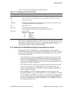
4.7.7.1 Probe Commands (Four Cycles)
Probes are always 4-cycle commands that contain a field to indicate a valid SysDc com-
mand. The format of the 4-cycle command is shown below.
Note: The SysAddIn_L[1:0] signal lines are optional and are used for memory
designs greater than 32GB. The position of the address bits matches the
selected format of the SysAddOut bus. The example below shows the bank
interleave format.
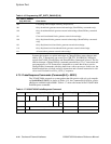
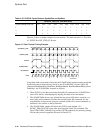
Table 4–19 shows the format of the system-to-21264/EV68A probe commands.
Table 4–19 System-to-21264/EV68A Probe Commands
SysAddIn_L[14:2] SysAddIn_L[1] SysAddIn_L[0]
Cycle 1 1 Probe[4:0] PA[34:28] PA[36] PA[38]
Cycle 2 PA[27:22], PA[12:6] PA[35] PA[37]
Cycle 3 0 SysDc[4:0] RVB RPB A ID[3:0] PA[40] PA[42]
Cycle 4 C PA[21:13], PA[5:3] PA[39] PA[41]


