21264/EV68A Hardware Reference Manual
Internal Architecture 2–39
Design Examples
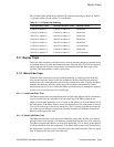
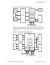
Figure 2–12 Typical Uniprocessor Configuration
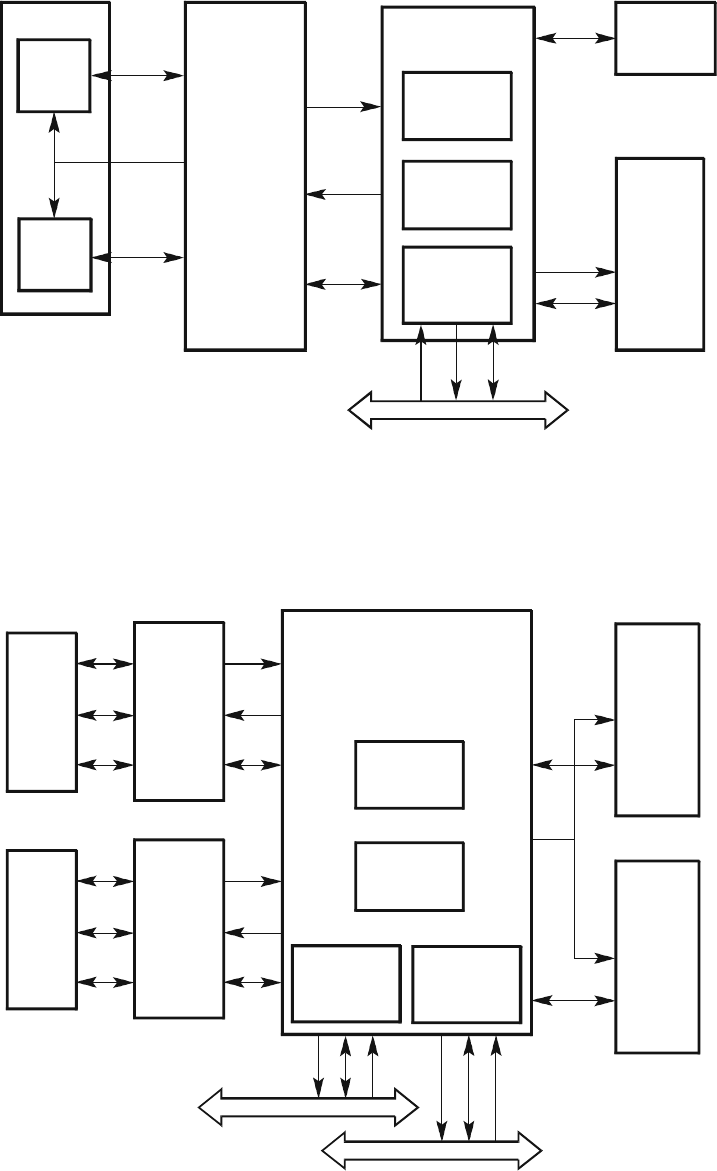
Figure 2–13 shows a typical multiprocessor system, each processor with a second-level
cache. Each interface controller must employ a duplicate tag store to maintain cache
coherency. This system configuration could be used in a networked database server
application.
Figure 2–13 Typical Multiprocessor Configuration
21264
Tag
Address
Out
Address
Address
In
Data
Data
L2 Cache
Ta g
Store
Data
Store
21272 Core
Lo
g
ic Chipset
Data Slice
Chips
Control
Chips
Host PCI
Bridge Chip
Duplicate
Tag Store
(Optional)
DRAM
Arrays
Address
Data
64-bit PCI Bus
FM-05573-EV67
64-bit PCI Bus
64-bit PCI Bus
21264
L2
Cache
21264
L2
Cache
21272 Core
Lo
g
ic Chipset
Control
Chip
Data Slice
Chips
Host PCI
Bridge Chip
Host PCI
Bridge Chip
DRAM
Arrays
Address
Data
DRAM
Arrays
Address
Data
FM-05574-EV67


