21264/EV68A Hardware Reference Manual
Internal Architecture 2–9
21264/EV68A Microarchitecture
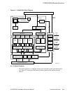
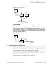
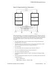
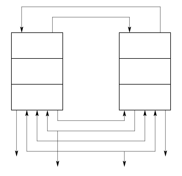
Figure 2–6 Integer Execution Unit—Clusters 0 and 1
Most instructions have 1-cycle latency for consumers that execute within the same clus-
ter. Also, there is another 1-cycle delay associated with producing a value in one cluster
and consuming the value in the other cluster. The instruction issue queue minimizes the
performance effect of this cross-cluster delay. The Ebox contains the following
resources:
• Four 64-bit adders that are used to calculate results for integer add instructions
(located in U0, U1, L0, and L1)
• The adders in the lower subclusters that are used to generate the effective virtual
address for load and store instructions (located in L0 and L1)
• Four logic units
• Two barrel shifters and associated byte logic (located in U0 and U1)
• Two sets of conditional branch logic (located in U0 and U1)
• Two copies of an 80-entry register file
• One pipelined multiplier (located in U1) with 7-cycle latency for all integer multiply
operations
• One fully-pipelined unit (located in U0), with 3-cycle latency, that executes the fol-
lowing instructions:
– CTLZ, CTPOP, CTTZ
– PERR, MINxxx, MAXxxx, UNPKxx, PKxx
L0
Register
U0
Load/Store Data
L1
Register
U1
Load/Store Data
iop_wr
iop_wr
eff_VA eff_VA
iop_wr
iop_wr
FM-05643.AI4


