2–18 Internal Architecture
21264/EV68A Hardware Reference Manual
Instruction Issue Rules
2.3.2 Ebox Slotting
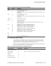
Instructions that are issued from the IQ, and could execute in either upper or lower
Ebox subclusters, are slotted to one pair or the other during the pipeline mapping stage
based on the instruction mixture in the fetch line. The codes that are used in Table 2–3
are as follows:
• U—The instruction only executes in an upper subcluster.
• L—The instruction only executes in a lower subcluster.
• E—The instruction could execute in either an upper or lower subcluster.
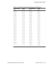
Table 2–3 defines the slotting rules. The table field Instruction Class 3, 2, 1 and 0 iden-
tifies each instruction’s location in the fetch line by the value of bits [3:2] in its PC.
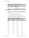
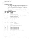
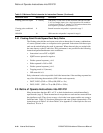
ftoi FST0, FST1, L0, L1 FTOIS, FTOIT
itof L0, L1 ITOFS, ITOFF, ITOFT
mx_fpcr FM Instructions that move data from the floating-point
control register
Table 2–3 Instruction Group Definitions and Pipeline Unit
Instruction Class
3210
Slotting
3210
Instruction Class
3210
Slotting
3210
EEEE ULUL LLLL LLLL
EEEL ULUL LLLU LLLU
EEEU ULLU LLUE LLUU
EELE ULLU LLUL LLUL
EELL UULL LLUU LLUU
EELU ULLU LUEE LULU
EEUE ULUL LUEL LUUL
EEUL ULUL LUEU LULU
EEUU LLUU LULE LULU
ELEE ULUL LULL LULL
ELEL ULUL LULU LULU
ELEU ULLU LUUE LUUL
ELLE ULLU LUUL LUUL
ELLL ULLL LUUU LUUU
ELLU ULLU UEEE ULUL
ELUE ULUL UEEL ULUL
ELUL ULUL UEEU ULLU
Table 2–2 Instruction Name, Pipeline, and Types (Continued)
Class
Name Pipeline Instruction Type


