21264/EV68A Hardware Reference Manual
xiii
Tables
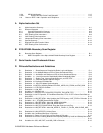
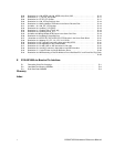
1–1 Integer Data Types . ....................................................... 1–2
2–1 PipelineAbortDelay(GCLKCycles)........................................... 2–16
2–2 InstructionName,Pipeline,andTypes......................................... 2–17
2–3 InstructionGroupDefinitionsandPipelineUnit................................... 2–18
2–4 InstructionClassLatencyinCycles............................................ 2–20
2–5 MinimumRetireLatenciesforInstructionClasses ................................ 2–21
2–6 InstructionsRetiredWithoutExecution......................................... 2–23
2–7 RulesforI/OAddressSpaceLoadInstructionDataMerging........................ 2–28
2–8 RulesforI/OAddressSpaceStoreInstructionDataMerging........................ 2–29
2–9 MAFMergingRules........................................................ 2–30
2–10 MemoryReferenceOrdering................................................. 2–30
2–11 I/OReferenceOrdering..................................................... 2–31
2–12 TB Fill Flow Example Sequence 1 ............................................ 2–34
2–13 TB Fill Flow Example Sequence 2 ............................................ 2–34
2–14 Floating-PointControlRegisterFields.......................................... 2–36
2–15 21264/EV68A AMASK Values................................................ 2–38
2–16 AMASKBitAssignments.................................................... 2–38
3–1 Signal Pin Types Definitions ................................................. 3–3
3–2 21264/EV68A Signal Descriptions ............................................ 3–3
3–3 21264/EV68A Signal Descriptions by Function. . ................................. 3–6
3–4 PinListSortedbySignalName............................................... 3–8
3–5 PinListSortedbyPGALocation.............................................. 3–12
3–6 Ground and Power (VSS and VDD) Pin List . . . ................................. 3–16
4–1 TranslationofInternalReferencestoExternalInterfaceReference................... 4–5
4–2 21264/EV68A-Supported Cache Block States . . ................................. 4–9
4–3 CacheBlockStateTransitions ............................................... 4–10
4–4 System Responses to 21264/EV68A Commands................................. 4–10
4–5 System Responses to 21264/EV68A Commands and Reactions..................... 4–11
4–6 SystemPortPins.......................................................... 4–17
4–7 ProgrammingValuesforSystemInterfaceClocks................................ 4–18
4–8 ProgramValuesforData-Sample/DriveCSRs................................... 4–18
4–9 ForwardedClocksandFrameClockRatio...................................... 4–19
4–10 BankInterleaveonCacheBlockBoundaryModeofOperation...................... 4–19
4–11 PageHitModeofOperation................................................. 4–20
4–12 21264/EV68A-to-System Command Fields Definitions. . ........................... 4–20
4–13 MaximumPhysicalAddressforShortBusFormat................................ 4–21
4–14 21264/EV68A-to-System Commands Descriptions................................ 4–21
4–15 ProgrammingINVAL_TO_DIRTY_ENABLE[1:0].................................. 4–23
4–16 ProgrammingSET_DIRTY_ENABLE[2:0]....................................... 4–24
4–17 21264/EV68A ProbeResponse Command ...................................... 4–24
4–18 ProbeResponse Fields Descriptions ........................................... 4–25
4–19 System-to-21264/EV68A Probe Commands..................................... 4–26
4–20 System-to-21264/EV68A Probe Commands Fields Descriptions ..................... 4–27
4–21 Data Movement Selection by Probe[4:3]. . ...................................... 4–27
4–22 Next Cache Block State Selection by Probe[2:0] ................................. 4–27
4–23 DataTransferCommandFormat ............................................. 4–28
4–24 SysDc[4:0]FieldDescription................................................. 4–29
4–25 SYSCLK Cycles Between SysAddOut and SysData............................... 4–32
4–26 CboxCSRSYSDC_DELAY[4:0]Examples ..................................... 4–33
4–27 FourTimingExamples ..................................................... 4–34
4–28 Data Wrapping Rules ...................................................... 4–36
4–29 SystemWrapandDeliverData............................................... 4–37
4–30 WrapInterleaveOrder...................................................... 4–37
4–31 WrapOrderforDouble-PumpedDataTransfers.................................. 4–38
4–32 21264/EV68A Commands with NXM Addresses and System Response ............... 4–39
4–33 21264/EV68A Response to System Probe and In-Flight Command Interaction .......... 4–41


