2–14 Internal Architecture
21264/EV68A Hardware Reference Manual
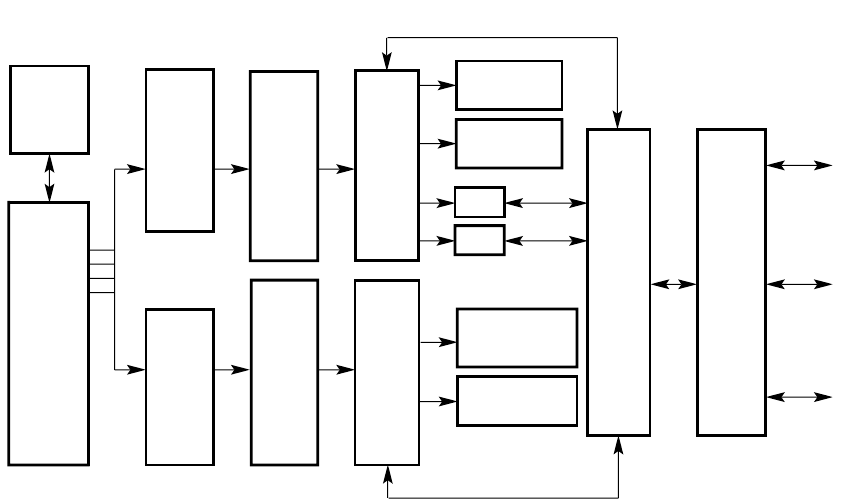
Pipeline Organization
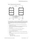
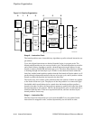
Figure 2–8 Pipeline Organization
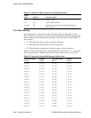
Stage 0 — Instruction Fetch
The branch predictor uses a branch history algorithm to predict a branch instruction tar-
get address.
Up to four aligned instructions are fetched from the Icache, in program order. The
branch prediction tables are also accessed in this cycle. The branch predictor uses tables
and a branch history algorithm to predict a branch instruction target address for one
branch or memory format JSR instruction per cycle. Therefore, the prefetcher is limited
to fetching through one branch per cycle. If there is more than one branch within the
fetch line, and the branch predictor predicts that the first branch will not be taken, it will
predict through subsequent branches at the rate of one per cycle, until it predicts a taken
branch or predicts through the last branch in the fetch line.
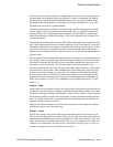
The Icache array also contains a line prediction field, the contents of which are applied
to the Icache in the next cycle. The purpose of the line predictor is to remove the pipe-
line bubble which would otherwise be created when the branch predictor predicts a
branch to be taken. In effect, the line predictor attempts to predict the Icache line which
the branch predictor will generate. On fills, the line predictor value at each fetch line is
initialized with the index of the next sequential fetch line, and later retrained by the
branch predictor if necessary.
Stage 1 — Instruction Slot
The Ibox maps four instructions per cycle from the 64KB 2-way set-predict Icache.
Instructions are mapped in order, executed dynamically, but are retired in order.
Branch
Predictor
Instruction
Cache
(64KB)
(2-Set)
Integer
Register
Rename
Map
Floating-
Point
Register
Rename
Map
Integer
Issue
Queue
(20)
Integer
Register
File
Floating-
Point
Issue
Queue
(15)
Floating-
Point
Register
File
ALU
Shifter
ALU Shifter
Multiplier
ALU
Address
Address
ALU
Floating-Point
Add, Divide,
and Square Root
Floating-Point
Multiply
64KB
Data
Cache
Bus
Interface
Unit
System
Bus
(64 Bits)
Cache
Bus
(128 Bits)
Physical
Address
(44 Bits)
Four
Instructions
FM-05575.AI4
0213456


