7–16 Initialization and Configuration
21264/EV68A Hardware Reference Manual
IEEE 1149.1 Test Port Reset
7.9 IEEE 1149.1 Test Port Reset
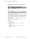
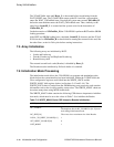
Signal Trst_L must be asserted when powering up the 21264/EV68A. Trst_L must not
be deasserted prior to assertion of DCOK_H. Trst_L can remain asserted during nor-
mal operation of the 21264/EV68A.
7.10 Reset State Machine
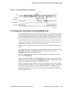
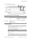
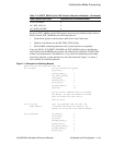
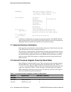
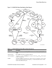
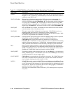
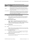
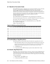
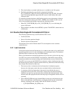
The state diagram in Figure 7–5 summarizes how the 21264/EV68A transitions into
running code. Each state is described in Table 7–11. Table 7–11 describes outputs and
approximate state transition equations. Note that there are implicit transitions from
each state to an appropriate down-ramp state when Reset_L is asserted.
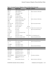
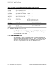
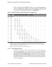
DTB_IS0 DTB invalidate single (array 0) X —
DTB_IS1 DTB invalidate single (array 1) X —
DTB_ASN0 DTB address space number 0 Cleared —
DTB_ASN1 DTB address space number 1 Cleared —
MM_STAT Memory management status X —
M_CTL Mbox control Cleared —
DC_CTL Dcache control DC_CTL[7:2] are cleared at reset.
DC_CTL[1:0] are set at power up.
DC_STAT Dcache status X Must be cleared in PALcode.
Cbox IPRs
C_DATA Cbox data X Must be read in PALcode.
C_SHFT Cbox shift control X —
Table 7–10 Internal Processor Registers at Power-Up Reset State (Continued)
Mnemonic Register Name Reset State Comments


