Two Port 10/100 Managed Ethernet Switch with 16-Bit Non-PCI CPU Interface
Datasheet
Revision 1.4 (08-19-08) 196 SMSC LAN9311/LAN9311i
DATASHEET
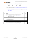
14.2.3.3 General Purpose I/O Interrupt Status and Enable Register (GPIO_INT_STS_EN)
This read/write register contains the GPIO interrupt status bits.
Writing a 1 to any of the interrupt status bits acknowledges and clears the interrupt. If enabled, these
interrupt bits are cascaded into bit 12 (GPIO) of the Interrupt Status Register (INT_STS). Writing a 1
to any of the interrupt enable bits will enable the corresponding interrupt as a source. Status bits will
still reflect the status of the interrupt source regardless of whether the source is enabled as an interrupt
in this register. Bit 12 (GPIO_EN) of the Interrupt Enable Register (INT_EN) must also be set in order
for an actual system level interrupt to occur. Refer to Chapter 5, "System Interrupts," on page 49 for
additional information.
Offset: 1E8h Size: 32 bits
BITS DESCRIPTION TYPE DEFAULT
31:28 RESERVED RO -
27:16
GPIO Interrupt Enable[11:0] (GPIO[11:0]_INT_EN)
When set, these bits enable the corresponding GPIO interrupt.
Note: The GPIO interrupts must also be enabled via bit 12 (GPIO_EN) of
the Interrupt Enable Register (INT_EN) in order to cause the
interrupt pin (IRQ) to be asserted.
R/W 0h
15:12
RESERVED RO -
11:0
GPIO Interrupt[11:0] (GPIO[11:0]_INT)
These signals reflect the interrupt status as generated by the GPIOs. These
interrupts are configured through the General Purpose I/O Configuration
Register (GPIO_CFG).
Note: As GPIO interrupts, GPIO inputs are level sensitive and must be
active greater than 40 nS to be recognized as interrupt inputs.
R/WC 0h


