Two Port 10/100 Managed Ethernet Switch with 16-Bit Non-PCI CPU Interface
Datasheet
SMSC LAN9311/LAN9311i 413 Revision 1.4 (08-19-08)
DATASHEET
14.5.4 Buffer Manager CSRs
This section details the Buffer Manager (BM) registers. These registers allow configuration and
monitoring of the switch buffer levels and usage. A list of the general switch CSRs and their
corresponding register numbers is included in Table 14.12.
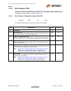
14.5.4.1 Buffer Manager Configuration Register (BM_CFG)
This register enables egress rate pacing and ingress rate discarding.
Register #: 1C00h Size: 32 bits
BITS DESCRIPTION TYPE DEFAULT
31:7 RESERVED RO -
6
BM Counter Test
When this bit is set, Buffer Manager (BM) counters that normally clear to 0
when read, will be set to 7FFF_FFFC when read.
R/W 0b
5
Fixed Priority Queue Servicing
When set, output queues are serviced with a fixed priority ordering. When
cleared, output queues are serviced with a weighted round robin ordering.
R/W 0b
4:2
Egress Rate Enable
When set, egress rate pacing is enabled. Bits 4,3,2 correspond to switch
ports 2,1,0 respectively.
R/W 0b
1
Drop on Yellow
When this bit is set, packets that exceed the Ingress Committed Burst Size
(colored Yellow) are subjected to random discard.
Note: See Section 14.5.3.26, "Switch Engine Ingress Rate Command
Register (SWE_INGRSS_RATE_CMD)," on page 396 for
information on configuring the Ingress Committed Burst Size.
R/W 0b
0
Drop on Red
When this bit is set, packets that exceed the Ingress Excess Burst Size
(colored Red) are discarded.
Note: See Section 14.5.3.26, "Switch Engine Ingress Rate Command
Register (SWE_INGRSS_RATE_CMD)," on page 396 for
information on configuring the Ingress Excess Burst Size.
R/W 0b


