Two Port 10/100 Managed Ethernet Switch with 16-Bit Non-PCI CPU Interface
Datasheet
Revision 1.4 (08-19-08) 444 SMSC LAN9311/LAN9311i
DATASHEET
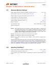
15.4 DC Specifications
Note 15.6 This specification applies to all IS type inputs and tri-stated bi-directional pins. Internal pull-
down and pull-up resistors add +/- 50uA per-pin (typical).
Note 15.7 XI can optionally be driven from a 25MHz single-ended clock oscillator.
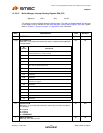
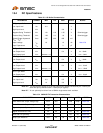
Table 15.3 I/O Buffer Characteristics
PARAMETER SYMBOL MIN TYP MAX UNITS NOTES
IS Type Input Buffer
Low Input Level
High Input Level
Negative-Going Threshold
Positive-Going Threshold
SchmittTrigger Hysteresis
(V
IHT
- V
ILT
)
Input Leakage
Input Capacitance
V
ILI
V
IHI
V
ILT
V
IHT
V
HYS
I
IN
C
IN
-0.3
1.01
1.39
345
-10
1.18
1.6
420
3.6
1.35
1.8
485
10
3
V
V
V
V
mV
uA
pF
Schmitt trigger
Schmitt trigger
Note 15.6
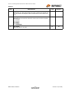
O8 Type Buffers
Low Output Level
High Output Level
V
OL
V
OH
VDD33IO - 0.4
0.4 V
V
I
OL
= 8mA
I
OH
= -8mA
OD8 Type Buffer
Low Output Level V
OL
0.4 V I
OL
= 8mA
O12 Type Buffer
Low Output Level
High Output Level
V
OL
V
OH
VDD33IO - 0.4
0.4 V
V
I
OL
= 12mA
I
OH
= -12mA
OD12 Type Buffer
Low Output Level V
OL
0.4 V I
OL
= 12mA
ICLK Type Buffer (XI Input)
Low Input Level
High Input Level
V
ILI
V
IHI
-0.3
1.4
0.5
3.6
V
V
Note 15.7
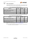
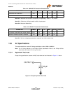
Table 15.4 100BASE-TX Transceiver Characteristics
PARAMETER SYMBOL MIN TYP MAX UNITS NOTES
Peak Differential Output Voltage High V
PPH
950 - 1050 mVpk Note 15.8
Peak Differential Output Voltage Low V
PPL
-950 - -1050 mVpk Note 15.8
Signal Amplitude Symmetry V
SS
98 - 102 % Note 15.8
Signal Rise and Fall Time T
RF
3.0 - 5.0 nS Note 15.8
Rise and Fall Symmetry T
RFS
--0.5nSNote 15.8
Duty Cycle Distortion D
CD
35 50 65 %
Note 15.9


