Two Port 10/100 Managed Ethernet Switch with 16-Bit Non-PCI CPU Interface
Datasheet
Revision 1.4 (08-19-08) 202 SMSC LAN9311/LAN9311i
DATASHEET
14.2.5 IEEE 1588
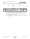
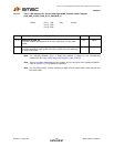
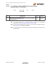
This section details the IEEE 1588 timestamp related registers. Each port of the LAN9311/LAN9311i
has a 1588 timestamp block with 8 related registers, 4 for transmit capture and 4 for receive capture.
These sets of registers are identical in functionality for each port, and thus their register descriptions
have been consolidated. In these cases, the register names will be amended with a lowercase “x” in
place of the port designation. The wildcard “x” should be replaced with “1”, “2”, or “MII” for the Port 1,
Port 2, and Port 0(Host MAC) respectively. A list of all the 1588 related registers can be seen in
Table 14.1. For more information on the IEEE 1588, refer to Chapter 11, "IEEE 1588 Hardware Time
Stamp Unit," on page 155.
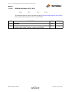
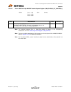
14.2.5.1 Port x 1588 Clock High-DWORD Receive Capture Register (1588_CLOCK_HI_RX_CAPTURE_x)
Note: The selection between Sync or Delay_Req packets is based on the corresponding
master/slave bit in the 1588 Configuration Register (1588_CONFIG).
Note: There are multiple instantiations of this register, one for each port of the LAN9311/LAN9311i.
Refer to Section 14.2.5 for additional information.
Note: For Port 0(Host MAC), receive is defined as data from the switch fabric, while transmit is to
the switch fabric.
Offset: Port 1: 100h Size: 32 bits
Port 2: 120h
Port 0: 140h
BITS DESCRIPTION TYPE DEFAULT
31:0 Timestamp High (TS_HI)
This field contains the high 32-bits of the timestamp taken on the receipt of
a 1588 Sync or Delay_Req packet.
RO 00000000h


