Two Port 10/100 Managed Ethernet Switch with 16-Bit Non-PCI CPU Interface
Datasheet
Revision 1.4 (08-19-08) 230 SMSC LAN9311/LAN9311i
DATASHEET
14.2.6 Switch Fabric
This section details the memory mapped System CSR’s which are related to the Switch Fabric. The
flow control of all three ports of the switch fabric can be configured via the memory mapped System
CSR’s MANUAL_FC_1, MANUAL_FC_2 and MANUAL_FC_MII. The MAC address used by the switch
for Pause frames is configured via the SWITCH_MAC_ADDRH and SWITCH_MAC_ADDRL registers.
In addition, the SWITCH_CSR_CMD, SWITCH_CSR_DATA and SWITCH_CSR_DIRECT_DATA
registers serve as a memory mapped accessible interface to the full range of otherwise inaccessible
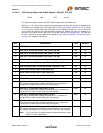
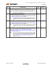
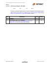
switch control and status registers. A list of all the switch fabric CSRs can be seen in Table 14.12. For
additional information on the switch fabric, including a full explanation on how to use the switch fabric
CSR interface registers, refer to Chapter 6, "Switch Fabric," on page 55. For detailed descriptions of
the Switch Fabric CSR’s that are accessible via these interface registers, refer to section Section 14.5,
"Switch Fabric Control and Status Registers".
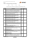
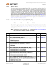
14.2.6.1 Port 1 Manual Flow Control Register (MANUAL_FC_1)
This read/write register allows for the manual configuration of the switch Port 1 flow control. This
register also provides read back of the currently enabled flow control settings, whether set manually
or Auto-Negotiated. Refer to Section 6.2.3, "Flow Control Enable Logic," on page 58 for additional
information.
Note: The flow control values in the PHY_AN_ADV_1 register (see Section 14.4.2.5, on page 295)
within the PHY are not affected by the values of this register.
Offset: 1A0h Size: 32 bits
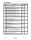
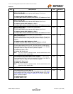
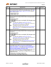
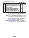
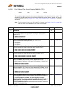
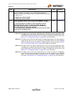
BITS DESCRIPTION TYPE DEFAULT
31:7 RESERVED RO -
6
Port 1 Backpressure Enable (BP_EN_1)
This bit enables/disables the generation of half-duplex backpressure on
switch Port 1.
0: Disable backpressure
1: Enable backpressure
R/W Note 14.4
5
Port 1 Current Duplex (CUR_DUP_1)
This bit indicates the actual duplex setting of switch Port 1.
0: Full-Duplex
1: Half-Duplex
RO Note 14.5
4
Port 1 Current Receive Flow Control Enable (CUR_RX_FC_1)
This bit indicates the actual receive flow setting of switch Port 1.
0: Flow control receive is currently disabled
1: Flow control receive is currently enabled
RO Note 14.5
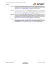
3
Port 1 Current Transmit Flow Control Enable (CUR_TX_FC_1)
This bit indicates the actual transmit flow setting of switch Port 1.
0: Flow control transmit is currently disabled
1: Flow control transmit is currently enabled
RO Note 14.5
2
Port 1 Full-Duplex Receive Flow Control Enable (RX_FC_1)
When the MANUAL_FC_1 bit is set, or Auto-Negotiation is disabled, this bit
enables/disables the detection of full-duplex Pause packets on switch Port 1.
0: Disable flow control receive
1: Enable flow control receive
R/W Note 14.6


