Two Port 10/100 Managed Ethernet Switch with 16-Bit Non-PCI CPU Interface
Datasheet
SMSC LAN9311/LAN9311i 263 Revision 1.4 (08-19-08)
DATASHEET
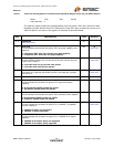
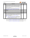
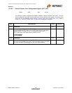
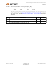
Note 14.47 The default value of this field is determined by the configuration strap auto_mdix_strap_2.
See Section 4.2.4, "Configuration Straps," on page 40 for more information.
Note 14.48 The default value of this field is determined by the configuration strap auto_mdix_strap_1.
See Section 4.2.4, "Configuration Straps," on page 40 for more information.
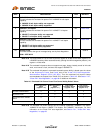
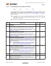
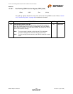
19:16
TX FIFO Size (TX_FIF_SZ)
This field sets the size of the TX FIFOs in 1KB values to a maximum of
14KB. The TX Status FIFO consumes 512 bytes of the space allocated by
TX_FIF_SIZ, and the TX Data FIFO consumes the remaining space
specified by TX_FIF_SZ. The minimum size of the TX FIFOs is 2KB (TX
Data FIFO and Status FIFO combined). The TX Data FIFO is used for both
TX data and TX commands.
The RX Status and Data FIFOs consume the remaining space, which is
equal to 16KB minus TX_FIF_SIZ. See section Section 9.7.3, "FIFO
Memory Allocation Configuration," on page 122 for more information.
R/W 5h
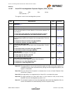
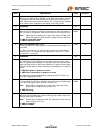
15:14
RESERVED RO -
13:12 RESERVED - This field must be written with 00b for proper operation. R/W 00b
11:1
RESERVED RO -
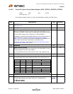
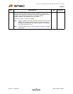
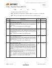
0
Soft Reset (SRST)
Writing 1 generates a software initiated reset to the Host Bus Interface, the
Host MAC, and System CSR’s below address 100h. The System CSR’s are
all reset except for any NASR bits. Soft reset also clears any TX or RX
errors in the Host MAC transmitter and receiver (TXE/RXE). This bit is self-
clearing. In order to reset all values, the Reset Control Register
(RESET_CTL) must be used.
Note: This bit will read high during assertion of DIGITAL_RST in the
Reset Control Register (RESET_CTL). The LAN9311/LAN9311i
must always be read at least once after power-up or reset to
ensure that write operations function correctly.
R/W
SC
0b
BITS DESCRIPTION TYPE DEFAULT


