


168 AMD Geode™ SC3200 Processor Data Book
Core Logic Module
32581C
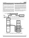
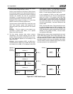
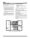
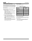
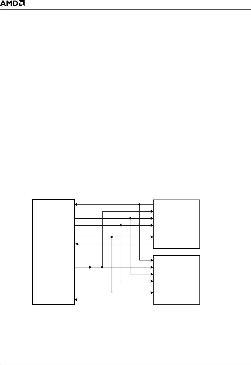
6.2.12.2 AC97 Codec Interface
The AC97 codec (e.g., LM4548) is the master of the serial
interface and generates the clocks to Core Logic module.
Figure 6-13 shows the signal connections between two
codecs and the SC3200:
• Codec1 can be AC97 Rev. 1.3 or higher compliant.
• Codec2 is optional, but must be compliant with AC97 2.0
or higher. (For specifics on the serial interface, refer to
the appropriate codec manufacturer’s data book.)
— SDATA_IN2 has wakeup capability. (See Section 5.6
"System Wakeup Control (SWC)" on page 114.)
— If SDATA_IN2 is not used it must be connected to
V
SS
.
— If an AMC97 codec is used (as Codec2), it should be
connected to SDATA_IN2 and SDATA_IN should be
connected to V
SS
.
• For PC speaker synthesis, the Core Logic module
outputs the PC speaker signal on the PC_BEEP pin
which is connected to the PC_BEEP input of the AC97
codec. Note that PC_BEEP is muxed with GPIO16 and
must be programmed via PMR[0] (see Table 4-2 on
page 70.)
Codec Configuration/Control Registers
The codec 32-bit related registers:
• GPIO Status and Control Registers
— Codec GPIO Status Register (F3BAR0+Memory
Offset 00h)
— Codec GPIO Control Register (F3BAR0+Memory
Offset 04h)
• Codec Status Register (F3BAR0+Memory Offset 08h)
• Codec Command Register (F3BAR0+Memory Offset
0Ch)
Codec GPIO Status and Control Registers:
The Codec GPIO Status and Control registers are used for
codec GPIO related tasks such as enabling a codec GPIO
interrupt to cause an SMI.
Codec Status Register:
The Codec Status register stores the codec status WORD.
It is updated every valid Status Word slot.
Codec Command Register:
The Codec Command register writes the control WORD to
the codec. By writing the appropriate control WORDs to
this port, the features of the codec can be controlled. The
contents of this register are written to the codec during the
Control Word slot.
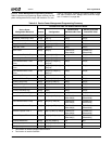
The bit formats for these registers are given in Table 6-38
"F3BAR0+Memory Offset: Audio Configuration Registers"
on page 262.
Figure 6-13. AC97 V2.0 Codec Signal Connections
BIT_CLK
PC_BEEP
SDATA_OUT
AC97_CLK
PC_BEEP
SDATA_OUT
SDATA_IN
Codec1
BIT_CLK
XTAL_I
SYNC SYNC
PC_BEEP
SDATA_OUT
SDATA_IN2
BIT_CLK
XTAL_I
SYNC
SDATA_IN2
Codec2
(Optional)
SDATA_IN
AMD Geode™
SC3200
Processor