


250 AMD Geode™ SC3200 Processor Data Book
Core Logic Module - SMI Status and ACPI Registers - Function 1
32581C
7 Reserved. Must be set to 0.
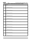
6 USB_STS. Indicates if PME was caused by a USB interrupt event.
0: No.
1: Yes.
Write 1 to clear.
For the PME to generate an SCI, set F1BAR1+I/O Offset 12h[6] = 1 and F1BAR1+I/O Offset 0Ch[0] = 1. (See Note 2 in the
general description of this register above.)
5 THRM_STS. Indicates if PME was caused by activity on THRM#.
0: No.
1: Yes.
Write 1 to clear.
For the PME to generate an SCI, set F1BAR1+I/O Offset 12h[5] = 1 and F1BAR1+I/O Offset 0Ch[0] = 1, (See Note 2 in the
general description of this register above,)
4 SMI_STS. Indicates if PME was caused by activity on the internal SMI# signal.
0: No.
1: Yes.
Write 1 to clear.
For the PME to generate an SCI, set F1BAR1+I/O Offset 12h[4] = 1 and F1BAR1+I/O Offset 0Ch[0] = 1. (See Note 2 in the
general description of this register above.)
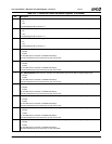
3 GPIO_STS. Indicates if PME was caused by activity on any of the GPIOs (GPIO47-GPIO32 and GPIO15-GPIO0).
0: No.
1: Yes.
Write 1 to clear.
For the PME to generate an SCI, set F1BAR1+I/O Offset 12h[3] = 1 and F1BAR1+I/O Offset 0Ch[0] = 1. (See Note 2 in the
general description of this register above).
F0BAR0+I/O Offset 08h/18h selects which GPIOs are enabled to generate a PME. In addition, the selected GPIO must be
enabled as an input (F0BAR0+I/O Offset 20h and 24h).
2:1 Reserved. Reads as 0.
0 PWR_U_REQ_STS. Indicates if PME was caused by a power-up request event from the SuperI/O module.
0: No.
1: Yes.
Write 1 to clear.
For the PME to generate an SCI, set F1BAR1+I/O Offset 12h[0] = 1 and F1BAR1+I/O Offset 0Ch[0] = 1. (See Note 2 in the
general description of this register above.)
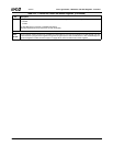
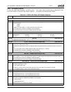
Table 6-34. F1BAR1+I/O Offset: ACPI Support Registers (Continued)
Bit Description