


AMD Geode™ SC3200 Processor Data Book 201
Core Logic Module - Bridge, GPIO, and LPC Registers - Function 0
32581C
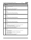
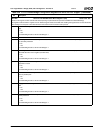
1 Idle Timers. Device idle timers.
0: Disable.
1: Enable.
Note: Disable at this level does not reload the timers on the enable. The timers are disabled at their current counts.
This bit has no affect on the Suspend Modulation register (F0 Index 94h).
Only applicable when in APM mode (F1BAR1+I/O Offset 0Ch[0] = 0) and not ACPI mode.
0 Power Management. Global power management.
0: Disable.
1: Enable.
This bit must be set to 1 immediately after POST for power management resources to function.
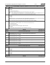
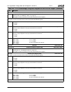
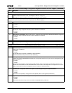
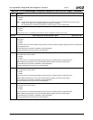
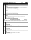
Index 81h Power Management Enable Register 2 (R/W) Reset Value: 00h
7 Video Access Idle Timer Enable. Turn on Video Idle Timer Count Register (F0 Index A6h) and generate an SMI when the
timer expires.
0: Disable.
1: Enable.
If an access occurs in the video address range (sets bit 0 of the GX1 module’s PSERIAL register) the timer is reloaded with
the programmed count.
Top level SMI status is reported at F1BAR0+I/O Offset 00h/02h[0].
Second level SMI status is reported at F0 Index 85h/F5h[7].
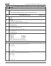
6 User Defined Device 3 (UDEF3) Idle Timer Enable. Turn on UDEF3 Idle Timer Count Register (F0 Index A4h) and gener-
ate an SMI when the timer expires.
0: Disable.
1: Enable.
If an access occurs in the programmed address range, the timer is reloaded with the programmed count.
UDEF3 address programming is at F0 Index C8h (base address register) and CEh (control register).
Top level SMI status is reported at F1BAR0+I/O Offset 00h/02h[0].
Second level SMI status is reported at F0 Index 85h/F5h[6].
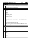
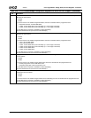
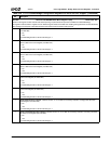
5 User Defined Device 2 (UDEF2) Idle Timer Enable. Turn on UDEF2 Idle Timer Count Register (F0 Index A2h) and gener-
ate an SMI when the timer expires.
0: Disable.
1: Enable.
If an access occurs in the programmed address range, the timer is reloaded with the programmed count.
UDEF2 address programming is at F0 Index C4h (base address register) and CDh (control register).
Top level SMI status is reported at F1BAR0+I/O Offset 00h/02h[0].
Second level SMI status is reported at F0 Index 85h/F5h[5].
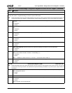
4 User Defined Device 1 (UDEF1) Idle Timer Enable. Turn on UDEF1 Idle Timer Count Register (F0 Index A0h) and gener-
ate an SMI when the timer expires.
0: Disable.
1: Enable.
If an access occurs in the programmed address range, the timer is reloaded with the programmed count.
UDEF1 address programming is at F0 Index C0h (base address register) and CCh (control register).
Top level SMI status is reported at F1BAR0+I/O Offset 00h/02h[0].
Second level SMI status is reported at F0 Index 85h/F5h[4].
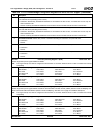
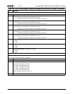
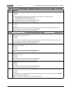
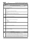
Table 6-29. F0: PCI Header/Bridge Configuration Registers for GPIO and LPC Support (Continued)
Bit Description