


AMD Geode™ SC3200 Processor Data Book 53
Signal Definitions
32581C
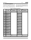
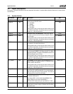
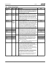
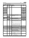
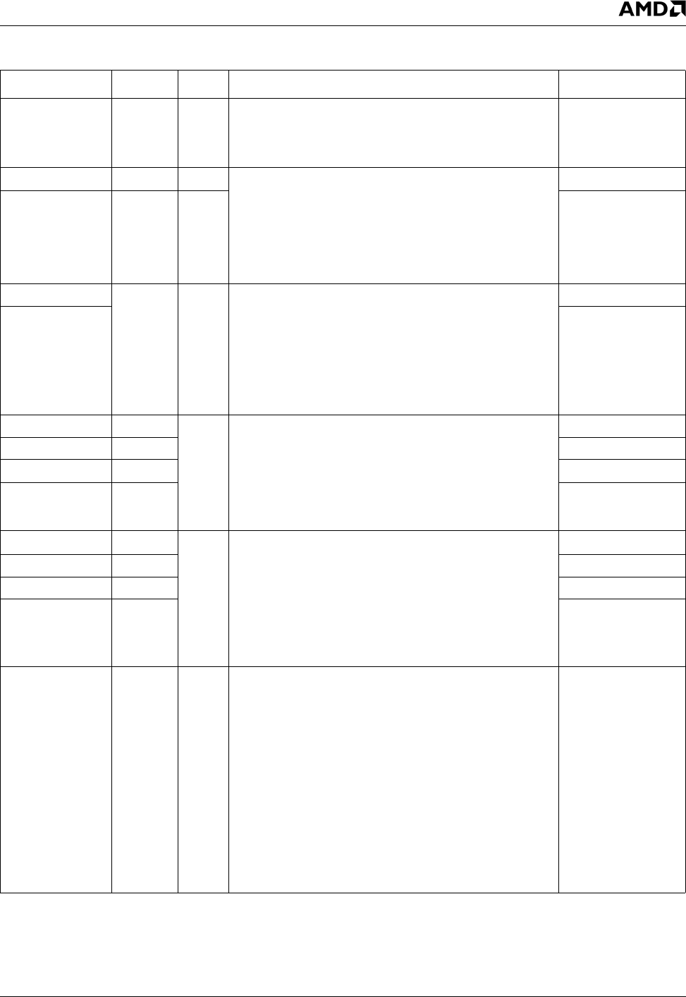
3.4.6 PCI Bus Interface Signals
Signal Name BalL No. Type Description Mux
PCICLK A7 I PCI Clock. PCICLK provides timing for all transactions
on the PCI bus. All other PCI signals are sampled on the
rising edge of PCICLK, and all timing parameters are
defined with respect to this edge.
---
PCICLK0 A4 O PCI Clock Outputs. PCICLK0 and PCICLK1 provide
clock drives for the system at 33 MHz. These clocks are
asynchronous to PCI signals. There is low skew between
all outputs. One of these clock signals should be con-
nected to the PCICLK input. All PCI clock users in the
system (including PCICLK) should receive the clock with
as low a skew as possible.
FPCI_MON (Strap)
PCICLK1 D6 O LPC_ROM (Strap)
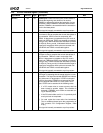
AD[31:24] See
Table 3-3
on page
40.
I/O Multiplexed Address and Data. A bus transaction con-
sists of an address phase in the cycle in which FRAME#
is asserted followed by one or more data phases. During
the address phase, AD[31:0] contain a physical 32-bit
address. For I/O, this is a byte address. For configuration
and memory, it is a DWORD address. During data
phases, AD[7:0] contain the least significant byte (LSB)
and AD[31:24] contain the most significant byte (MSB).
D[7:0]
AD[23:0] A[23:0]
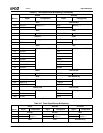
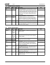
C/BE3# H4 I/O Multiplexed Command and Byte Enables. During the
address phase of a transaction when FRAME# is active,
C/BE[3:0]# define the bus command. During the data
phase, C/BE[3:0]# are used as byte enables. The byte
enables are valid for the entire data phase and determine
which byte lanes carry meaningful data. C/BE0# applies
to byte 0 (LSB) and C/BE3# applies to byte 3 (MSB).
D11
C/BE2# F3 D10
C/BE1# J2 D9
C/BE0# L1 D8
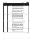
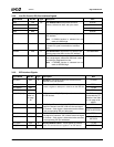
INTA# D26 I PCI Interrupts. The SC3200 provides inputs for the
optional “level-sensitive” PCI interrupts (also known in
industry terms as PIRQx#). These interrupts can be
mapped to IRQs of the internal 8259A interrupt control-
lers using PCI Interrupt Steering Registers 1 and 2
(F0 Index 5Ch and 5Dh).
Note: If selected as INTC# or INTD# function(s) but not
used, tie INTC# and INTD# high.
---
INTB# C26 ---
INTC# C9 GPIO19+IOCHRDY
INTD# AA2 IDE_DATA7
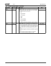
PAR J4 I/O Parity. Parity generation is required by all PCI agents.
The master drives PAR for address- and write-data
phases. The target drives PAR for read-data phases. Par-
ity is even across AD[31:0] and C/BE[3:0]#.
For address phases, PAR is stable and valid one PCI
clock after the address phase. It has the same timing as
AD[31:0] but is delayed by one PCI clock.
For data phases, PAR is stable and valid one PCI clock
after either IRDY# is asserted on a write transaction or
after TRDY# is asserted on a read transaction.
Once PAR is valid, it remains valid until one PCI clock
after the completion of the data phase. (Also see
PERR#.)
D12