


AMD Geode™ SC3200 Processor Data Book 333
Video Processor Module - Video Processor Registers - Function 4
32581C
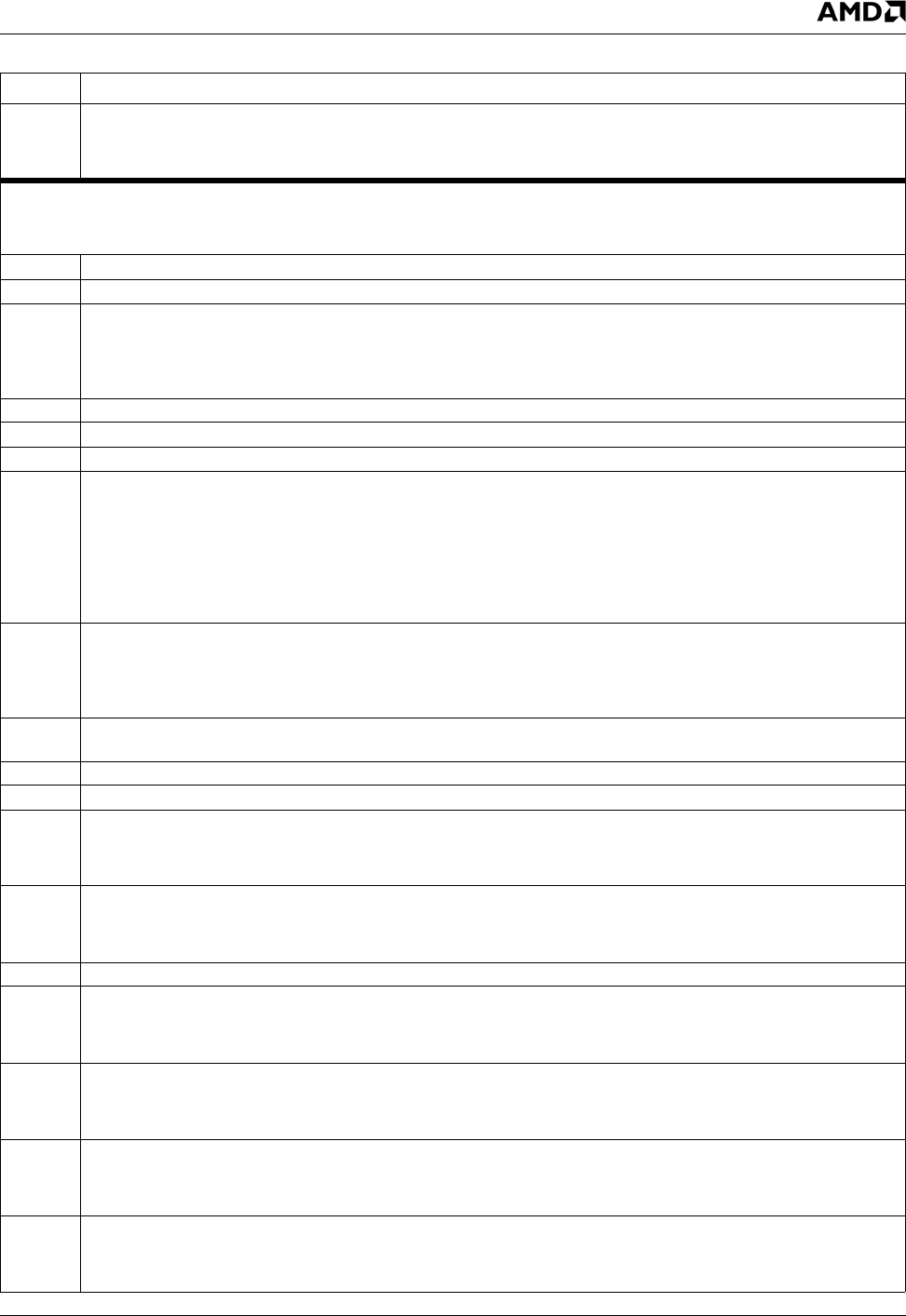
0 VID_EN (Video Enable). Enables video acceleration hardware.
0: Disable (reset) video module.
1: Enable.
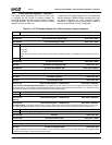
Offset 04h-07h Display Configuration Register (R/W) Reset Value: x0000000h
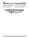
General configuration register for display control. This register is also used to determine how graphics and video data are to be com-
bined in the display on the output device.
31 Reserved. Write as read.
30:28 Reserved.
27 FP_ON_STATUS (Flat Panel On Status). (Read Only) Shows whether power to the attached flat panel is on or off. This bit
transitions at the end of the power-up or power-down sequence.
0: Power to the flat panel is off.
1: Power to the flat panel is on.
26 Reserved. Set to 0.
25 Reserved. Must be set to 0.
24:22 Reserved. Set to 0.
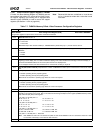
21 GV_GAMMA_SEL (Graphics or Video Gamma Source Data). Selects whether the graphics or video data goes to the
Gamma Correction RAM. GAMMA_EN (F4BAR0+Memory Offset 28h[0]) must be enabled for the selected data source to
pass through the Gamma Correction RAM.
0: Graphics data to Gamma Correction RAM.
1: Video data to Gamma Correction RAM.
Note: Gamma Correction is always in the RGB domain for graphics data.
Gamma Correction can be in the YUV or RGB domain for video data.
20 COLOR_CHROMA_SEL (Color or Chroma Key Select). Selects whether the graphics is used for color keying or the video
data stream is used for chroma keying.
0: Graphics data is compared to the color key.
1: Video data is compared to the chroma key.
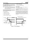
19:17 PWR_SEQ_DLY (Power Sequence Delay). Selects the number of frame periods that transpire between successive transi-
tions of the power sequence control lines.
16:14 Reserved. Write as read.
13:8 Reserved. Write as read.
7 FP_DATA_EN (Flat Panel Output Enable). Controls the data, data-enable, clock and sync output signals.
0: Flat panel data outputs are forced to zero depending on the value of bit 3 (BL_EN). Bit 6 (FP_PWR_EN) is ignored.
1: Flat panel outputs are forced to zero until power-up, and later, data outputs are subject to the value of bit 3 (BL_EN).
6 FP_PWR_EN (Flat Panel Power Enable). Changing this bit initiates a flat panel power-up or power-down.
0-to-1: Power-up flat panel.
1-to-0: Power-down flat panel.
5:4 Reserved.
3 BL_EN (Blank Enable). Controls blanking of TFT data.
0: TFT data is constantly blanked.
1: TFT data is blanked normally (i.e., during horizontal and vertical blank).
2 VSYNC_EN (Vertical Sync Enable). Enables/disables display vertical sync (used for VESA DPMS support).
0: Disable.
1: Enable.
1 HSYNC_EN (Horizontal Sync Enable). Enables/disables display horizontal sync (used for VESA DPMS support).
0: Disable.
1: Enable.
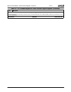
0 TFT_EN (TFT Enable). Enables the TFT control logic and is also used to reset the TFT control logic.
0: Reset TFT control logic.
1: Enable TFT control logic.
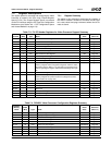
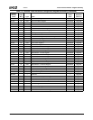
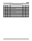
Table 7-7. F4BAR0+Memory Offset: Video Processor Configuration Registers (Continued)
Bit Description