AMD Geode™ SC3200 Processor Data Book 339
Video Processor Module - Video Processor Registers - Function 4
32581C
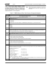
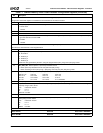
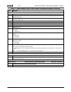
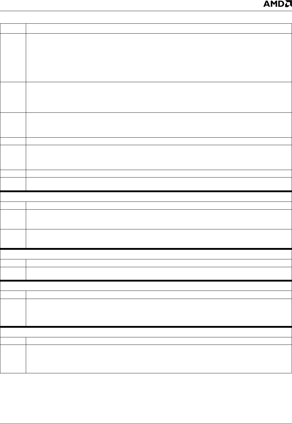
8 GFX_INS_VIDEO (Graphics Inside Video). This bit works in conjunction with bit COLOR_CHROMA_SEL (F4BAR0+Mem-
ory Offset 4Ch[20]). COLOR_CHROMA_SEL selects whether the graphics is used for color keying or the video data stream
is used for chroma keying. If COLOR_CHROMA_SEL = 0, graphics data is compared to the color key. If
COLOR_CHROMA_SEL = 1, video data is compared to the chroma key.
0: Outside the alpha windows, graphics or video is displayed depending on the result of the color key comparison.
1: Outside the alpha windows, only video is displayed (if COLOR_CHROMA_SEL = 0) or only graphics is displayed (if
COLOR_CHROMA_SEL = 1) color key comparison is not performed outside the alpha windows.
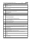
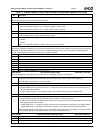
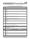
7 VID_WIN_PUSH_EN (Video Window Push Enable). Video window repositioning at an offset of 1 line below the pro-
grammed value. Facilitates line rate matching in both fields.
0: Disable. (Default)
1: Enable.
6 TOP_LINE_IN_ODD (Top Line in Odd Field). Allows selection of what field the top line is in.
0: Top line is in even field. (Default)
1: Top line is in odd field.
5 Reserved.
4 INSERT_EN (Insert Enable). When this bit is set, the odd frame is shifted with respect to the even frame.
0: No shifting occurs.
1: The odd frame is shifted according to the offset specified in bits [2:0].
3 Reserved.
2:0 OFFSET (Vertical Scaler Offset). For a non-interlaced video stream and when bob de-interlacing is used, program a value
of 100 (i.e., shift one line); otherwise, leave at 000.
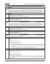
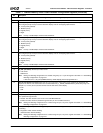
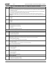
Offset 50h-53h Cursor Color Key Register (R/W) Reset Value: 00000000h
31:29 Reserved.
28:24 COLOR_REG_OFFSET (Cursor Color Register Offset). This field indicates a bit in the incoming graphics stream. It is
used to indicate which of the two possible cursor color registers should be used for color key matches for the bits in the
graphics stream.
23:0 CUR_COLOR_KEY (Cursor Color Key). Specifies the 24-bit RGB value of the cursor color key. The incoming graphics
stream is compared with this value. If a match is detected, the pixel is replaced by a 24-bit value from one of the Cursor
Color registers.
Offset 54h-57h Cursor Color Mask Register (R/W) Reset Value: 00000000h
31:24 Reserved
23:0 CUR_COLOR_MASK (Cursor Color Mask). This mask is a 24-bit value. Zeroes in the mask cause the corresponding bits
in the incoming graphics stream to be ignored.
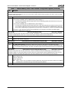
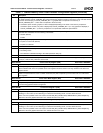
Offset 58h-5Bh Cursor Color Register 1 (R/W) Reset Value: 00000000h
31:24 Reserved
23:0 CUR_COLOR_REG1 (Cursor Color Register 1). Specifies a 24-bit cursor color value. This is an RGB value (for RGB
blending) or a YUV value (for YUV blending). In interlaced YUV blending mode, Y/2 value should be used.
This is one of two possible cursor color values. The COLOR_REG_OFFSET bits (F4BAR0+Memory Offset 50h[28:24])
determine a bit of the graphics data that if even, selects this color to be used.
Offset 5Ch-5Fh Cursor Color Register 2 (R/W) Reset Value: 00000000h
31:24 Reserved
23:0 CUR_COLOR_REG2 (Cursor Color Register 2). Specifies a 24-bit cursor color value. This is an RGB value (for RGB
blending) or a YUV value (for YUV blending). In interlaced YUV blending mode, Y/2 value should be used.
This is one of two possible cursor color values. The COLOR_REG_OFFSET bits (F4BAR0+Memory Offset 50h[28:24])
determine a bit of the graphics data that if even, selects this color to be used.
Table 7-7. F4BAR0+Memory Offset: Video Processor Configuration Registers (Continued)
Bit Description


