


AMD Geode™ SC3200 Processor Data Book 357
Electrical Specifications
32581C
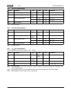
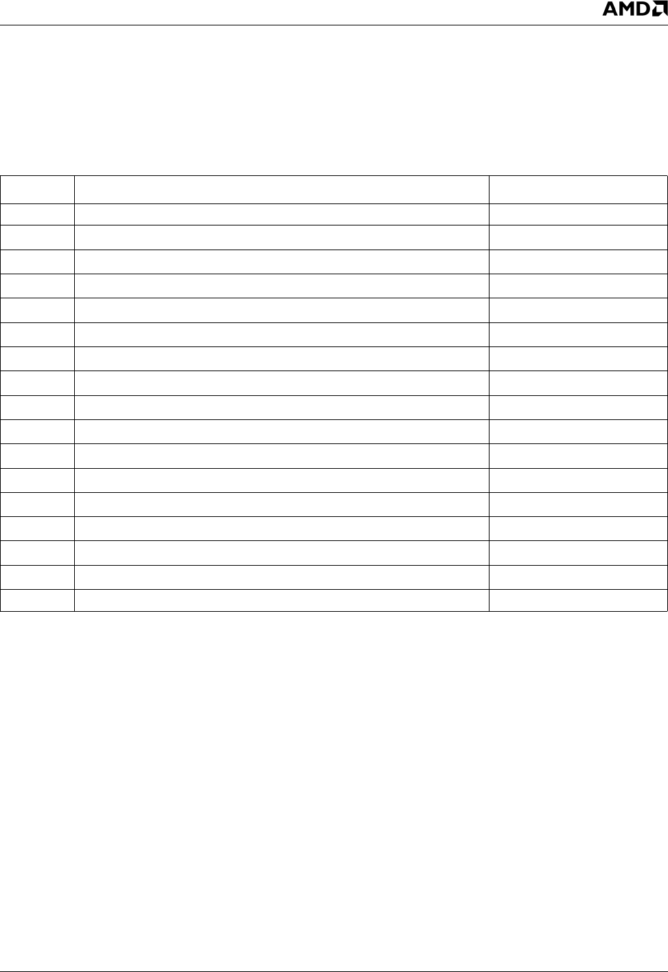
9.2 DC Characteristics
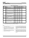
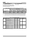
Table 9-10 describes the signal buffer types of the SC3200.
(See Table 3-2 "BGD432 Ball Assignment - Sorted by Ball
Number" on page 29 and Table 3-2 "BGU481 Ball Assign-
ment - Sorted by Ball Number" on page 29) for each sig-
nal’s buffer type.)
The subsections that follows provide detailed DC charac-
teristics according to buffer type.
Table 9-10. Buffer Types
Symbol Description Reference
Diode Diodes only, no buffer ---
IN
AB
Input, ACCESS.bus compatible with Schmitt Trigger Section 9.2.1
IN
BTN
Input, TTL compatible with Schmitt Trigger, low leakage Section 9.2.2
IN
PCI
Input, PCI compatible Section 9.2.3
IN
STRP
Input, Strap ball (min V
IH
is 0.6V
IO
) with weak pull-down Section 9.2.4
IN
T
Input, TTL compatible Section 9.2.5
IN
TS
Input, TTL compatible with Schmitt Trigger type 200 mV Section 9.2.6
IN
TS1
Input, with Schmitt Trigger type 200 mV Section 9.2.7
IN
USB
Input, USB compatible Section 9.2.8
O
AC97
Output, Totem-Pole, AC97 compatible Section 9.2.9
OD
n
Output, Open-Drain, capable of sinking n mA.Note 1 Section 9.2.10
OD
PCI
Output, Open-Drain, PCI compatible Section 9.2.11
O
p/n
Output, Totem-Pole, capable of sourcing p mA and sinking n mA Section 9.2.12
O
PCI
Output, PCI compatible, TRI-STATE Section 9.2.13
O
USB
Output, USB compatible Section 9.2.14
TS
p/n
Output, TRI-STATE, capable of sourcing p mA and sinking n mA Section 9.2.15
WIRE Wire, no buffer ---
Note 1.Output from these signals is open-drain and cannot be forced high.