


68 AMD Geode™ SC3200 Processor Data Book
Signal Definitions
32581C
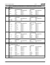
3.4.20 Power, Ground and No Connections
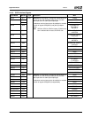
1
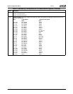
Signal Name Ball No. Type Description
AV
SSPLL2
C16 GND Analog PLL2 Ground Connection.
AV
SSPLL3
AK3 GND Analog PLL3 Ground Connection.
V
PLL2
A17 PWR 3.3V PLL2 Analog Power Connection. Low noise power for PLL2 and
PLL5.
V
PLL3
AJ4 PWR 3.3V PLL3 Analog Power Connection. Low noise power for PLL3,
PLL4, and PLL6.
AV
CCUSB
D27 PWR 3.3V Analog USB Power Connection. Low noise power.
AV
SSUSB
C27 GND Analog USB Ground Connection.
V
BAT
AL3 PWR Battery. Provides battery back-up to the RTC and ACPI registers, when
V
SB
is lower than the minimum value (see Table 9-3 on page 352). The
ball is connected to the internal logic through a series resistor for UL pro-
tection. If battery backup is not desired, connect V
BAT
to V
SS
.
V
SB
AL5 PWR 3.3V Standby Power Supply. Provides power to the Real-Time Clock
(RTC) and ACPI circuitry while the main power supply is turned off.
V
SBL
AL6 PWR 1.8V Standby Power Supply. Provides power to the internal logic while
the main power supply is turned off. This signal requires a 0.1 μF bypass
capacitor to V
SS
. This supply must be present when V
SB
is present.
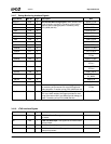
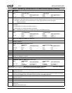
V
CORE
See Table 3-3
on page 40.
(Total of 29)
PWR 1.8V Core Processor Power Connections.
V
IO
See Table 3-3
on page 40.
(Total of 46)
PWR 3.3V I/O Power Connections.
V
SS
See Table 3-3
on page 40.
(Total of 96)
GND Ground Connections.
NC See Table 3-3
on page 40.
(Total of 13)
--- No Connections. These lines should be left disconnected. Connecting a
pull-up/-down resistor or to an active signal could cause unexpected
results and possible malfunctions.
1. All power sources except V
BAT
must be connected, even if the function is not used.