


220 AMD Geode™ SC3200 Processor Data Book
Core Logic Module - Bridge, GPIO, and LPC Registers - Function 0
32581C
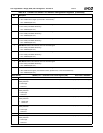
3 Keyboard/Mouse Access Trap SMI Status. Indicates whether or not an SMI was caused by a trapped I/O access to the
keyboard or mouse.
0: No.
1: Yes.
To enable SMI generation, set F0 Index 82h[3] = 1.
2 Parallel/Serial Access Trap SMI Status. Indicates whether or not an SMI was caused by a trapped I/O access to either the
serial or parallel ports.
0: No.
1: Yes.
To enable SMI generation, set F0 Index 82h[2] =1.
1 Floppy Disk Access Trap SMI Status. Indicates whether or not an SMI was caused by a trapped I/O access to the floppy
disk.
0: No.
1: Yes.
To enable SMI generation, set F0 Index 82h[1] = 1.
0 Primary Hard Disk Access Trap SMI Status. Indicates whether or not an SMI was caused by a trapped I/O access to the
primary hard disk.
0: No.
1: Yes.
To enable SMI generation, set F0 Index 82h[0] = 1.
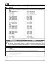
Index F7h Second Level PME/SMI Status Register 4 (RC) Reset Value: 00h
The bits in this register contain second level status reporting. Top level status is reported in F1BAR0+I/O Offset 00h/02h[0].
Reading this register clears the status at both the second and top levels except for bit 7 which has a third level of status reporting at
F0BAR0+I/O 0Ch/1Ch.
A read-only “Mirror” version of this register exists at F0 Index 87h. If the value of the register must be read without clearing the SMI
source (and consequently de-asserting SMI), F0 Index 87h can be read instead.
7 GPIO Event SMI Status (Read Only, Read does not Clear). Indicates whether or not an SMI was caused by a transition of
any of the GPIOs (GPIO47-GPIO32 and GPIO15-GPIO0).
0: No.
1: Yes.
To enable SMI generation, set F1BAR1+I/O Offset 0Ch[0] = 0.
F0BAR0+I/O Offset 08h/18h selects which GPIOs are enabled to generate a PME and setting F1BAR1+I/O Offset 0Ch[0] =
0 enables the PME to generate an SMI. In addition, the selected GPIO must be enabled as an input (F0BAR0+I/O Offset
20h and 24h).
The next level (third level) of SMI status is at F0BAR0+I/O 0Ch/1Ch.
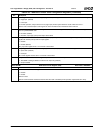
6 Thermal Override SMI Status. Indicates whether or not an SMI was caused by an assertion of the THRM#.
0: No.
1: Yes.
To enable SMI generation set F0 Index 83h[4] = 1.
5:4 Reserved. Read as 0.
3 SIO PWUREQ SMI Status. Indicates whether or not an SMI was caused by a power-up event from the SIO.
0: No.
1: Yes.
A power-up event is defined as any of the following events/activities:
—RI2#
—SDATA_IN2
— IRRX1 (CEIR)
To enable SMI generation, set F1BAR1+I/O Offset 0Ch[0] = 0.
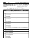
Table 6-29. F0: PCI Header/Bridge Configuration Registers for GPIO and LPC Support (Continued)
Bit Description