342 AMD Geode™ SC3200 Processor Data Book
Video Processor Module - Video Processor Registers - Function 4
32581C
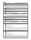
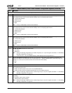
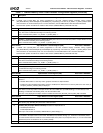
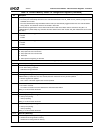
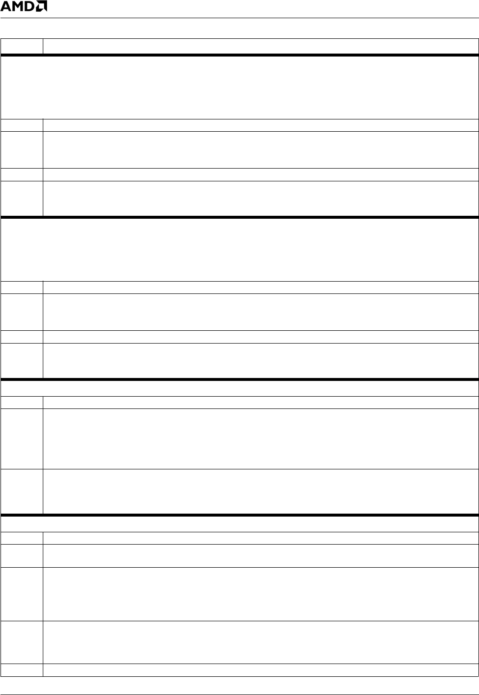
Offset 80h-83h Alpha Window 3 X Position Register (R/W) Reset Value: 00000000h
Note: H_TOTAL and H_SYNC_END are values programmed in the GX1 module’s Display Controller Timing registers
(GX_BASE+Memory Offset 8330h[26:19] and 8338h[10:3], respectively). The value of (H_TOTAL – H_SYNC_END) is some-
times referred to as “horizontal back porch”. For more information, see the AMD Geode™ GX1 Processor Data Book.
Note: Desired screen position should not be outside a video window (F4BAR0+Memory Offset 08h and 0Ch).
31:27 Reserved.
26:16 ALPHA3_X_END (Alpha Window 3 Horizontal End). Determines the horizontal end position of Alpha Window 3 (not inclu-
sive). This value is calculated according to the following formula:
Value = Desired screen position + (H_TOTAL – H_SYNC_END) – 1.
15:11 Reserved.
10:0 ALPHA3_X_START (Alpha Window 3 Horizontal Start). Determines the horizontal start position of Alpha Window 3. This
value is calculated according to the following formula:
Value = Desired screen position + (H_TOTAL – H_SYNC_END) – 2.
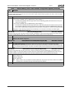
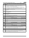
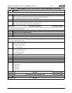
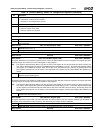
Offset 84h-87h Alpha Window 3 Y Position Register (R/W) Reset Value: 00000000h
Note: V_TOTAL and V_SYNC_END are values programmed in the GX1 module’s Display Controller Timing registers
(GX_BASE+Memory Offset 8340h[26:16] and 8348h[26:16], respectively). The value of (V_TOTAL – V_SYNC_END) is some-
times referred to as “vertical back porch”. For more information, see the AMD Geode™ GX1 Processor Data Book.
Desired screen position should not be outside a video window (F4BAR0+Memory Offset 08h and 0Ch).
31:27 Reserved
26:16 ALPHA3_Y_END (Alpha Window 3 Vertical End). Determines the vertical end position of Alpha Window 3 (not inclusive).
This value is calculated according to the following formula:
Value = Desired screen position + (V_TOTAL – V_SYNC_END) + 2.
15:11 Reserved
10:0 ALPHA3_Y_START (Alpha Window 3 Vertical End). Determines the vertical start position of Alpha Window 3. This value
is calculated according to the following formula:
Value = Desired screen position + (V_TOTAL – V_SYNC_END) + 1.
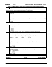
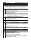
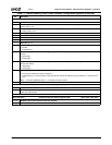
Offset 88h-8Bh Alpha Window 3 Color Register (R/W) Reset Value: 00000000h
31:25 Reserved.
24 ALPHA3_COLOR_REG_EN (Alpha Window 3 Color Register Enable). Enable bit for the color key matching in Alpha
Window 3.
0: Disable. Where there is a color key match, graphics and video are alpha-blended.
1: Enable. If this bit is enabled and the alpha window is enabled, then where there is a color key match, the color value (in
bits [23:0], ALPHA3_COLOR_REG) is displayed.
23:0 ALPHA3_COLOR_REG (Alpha Window 3 Color Register). Specifies the color to be displayed inside Alpha Window 3
when there is a color key match in the alpha window. This is an RGB value (for RGB blending) or a YUV value (for YUV
blending). In Interlaced YUV blending mode, Y/2 value should be used.
This color is only displayed if the alpha window is enabled and the bit 24 (ALPHA3_COLOR_REG_EN) is enabled.
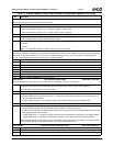
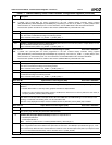
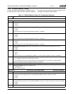
Offset 8Ch-8Fh Alpha Window 3 Control Register (R/W) Reset Value: 00000000h
31:18 Reserved
17 LOAD_ALPHA (Load Alpha Value). (Write Only) When set to 1, this bit causes the Video Processor to load the alpha
value (in bits [7:0], ALPHA3_VAL) at the start of the next frame.
16 ALPHA3_WIN_EN (Alpha Window 3 Enable). Enable bit for Alpha Window 3.
0: Disable Alpha Window 3.
1: Enable Alpha Window 3.
Valid only if video window is enabled (F4BAR0+Memory Offset 00h[0] = 1)
15:8 ALPHA3_INCR (Alpha Window 3 Increment). Specifies the alpha value increment/decrement. This is a signed 8-bit value
that is added to the alpha value for each frame. The MSB (bit 15) indicates the sign (i.e., increment or decrement). When
this value reaches either the maximum or the minimum alpha value (255 or 0) it keeps that value (i.e., it is not incremented/
decremented) until it is reloaded via bit 17 (LOAD_ALPHA).
7:0 ALPHA3_VAL (Alpha Window 3 Value). Specifies the alpha value to be used for this window.
Table 7-7. F4BAR0+Memory Offset: Video Processor Configuration Registers (Continued)
Bit Description


