


AMD Geode™ SC3200 Processor Data Book 197
Core Logic Module - Bridge, GPIO, and LPC Registers - Function 0
32581C
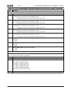
4 Secondary IDE Controller Positive Decode. Selects PCI positive or subtractive decoding for accesses to I/O ports 170h-
177h and 376h-377h (excluding writes to 377h).
0: Subtractive. Subtractively decoded IDE addresses are forwarded to the PCI slot bus. If a master abort occurs, they are
then forwarded to ISA.
1: Positive. Positively decoded IDE addresses are forwarded to the internal IDE controller and then to the IDE bus.
3 Primary IDE Controller Positive Decode. Selects PCI positive or subtractive decoding for accesses to I/O ports 1F0h-
1F7h and 3F6h-3F7h (excluding writes to 3F7h).
0: Subtractive. Subtractively decoded IDE addresses are forwarded to the PCI slot bus. If a master abort occurs, they are
then forwarded to ISA.
1: Positive. Positively decoded IDE addresses are forwarded to the internal IDE controller and then to the IDE bus.
2 LPT3 Positive Decode. Selects PCI positive or subtractive decoding for accesses to I/O ports 278h-27Fh.
0: Subtractive.
1: Positive.
1 LPT2 Positive Decode. Selects PCI positive or subtractive decoding for accesses to I/O ports 378h-37Fh.
0: Subtractive.
1: Positive.
0 LPT1 Positive Decode. Selects PCI positive or subtractive decoding for accesses to I/O ports 3BCh-3BFh
0: Subtractive.
1: Positive.
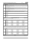
Index 5Ch PCI Interrupt Steering Register 1 (R/W) Reset Value: 00h
Indicates target interrupts for signals INTB# and INTA#.
Note: The target interrupt must first be configured as level sensitive via I/O Ports 4D0h and 4D1h in order to maintain PCI interrupt
compatibility.
7:4 INTB# (Ball C26) Target Interrupt.
0000: Disable 0100: IRQ4 1000: Reserved 1100: IRQ12
0001: IRQ1 0101: IRQ5 1001: IRQ9 1101: Reserved
0010: Reserved 0110: IRQ6 1010: IRQ10 1110: IRQ14
0011: IRQ3 0111: IRQ7 1011: IRQ11 1111: IRQ15
3:0 INTA# (Ball D26) Target Interrupt.
0000: Disable 0100: IRQ4 1000: Reserved 1100: IRQ12
0001: IRQ1 0101: IRQ5 1001: IRQ9 1101: Reserved
0010: Reserved 0110: IRQ6 1010: IRQ10 1110: IRQ14
0011: IRQ3 0111: IRQ7 1011: IRQ11 1111: IRQ15
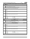
Index 5Dh PCI Interrupt Steering Register 2 (R/W) Reset Value: 00h
Indicates target interrupts for signals INTD# and INTC#. Note that INTD# is muxed with IDE_DATA7 (selection made via PMR[24]) and
INTC# is muxed with GPIO19+IOCHRDY (selection made via PMR[9,4]). See Table 4-2 on page 70 for PMR bit descriptions.
Note: The target interrupt must first be configured as level sensitive via I/O Ports 4D0h and 4D1h in order to maintain PCI interrupt
compatibility.
7:4 INTD# (Ball AA2) Target Interrupt.
0000: Disable 0100: IRQ4 1000: Reserved 1100: IRQ12
0001: IRQ1 0101: IRQ5 1001: IRQ9 1101: Reserved
0010: Reserved 0110: IRQ6 1010: IRQ10 1110: IRQ14
0011: IRQ3 0111: IRQ7 1011: IRQ11 1111: IRQ15
3:0 INTC# (Ball C9) Target Interrupt.
0000: Disable 0100: IRQ4 1000: Reserved 1100: IRQ12
0001: IRQ1 0101: IRQ5 1001: IRQ9 1101: Reserved
0010: Reserved 0110: IRQ6 1010: IRQ10 1110: IRQ14
0011: IRQ3 0111: IRQ7 1011: IRQ11 1111: IRQ15
Index 5Eh-5Fh Reserved Reset Value: 00h
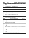
Table 6-29. F0: PCI Header/Bridge Configuration Registers for GPIO and LPC Support (Continued)
Bit Description