


52 AMD Geode™ SC3200 Processor Data Book
Signal Definitions
32581C
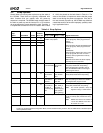
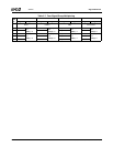
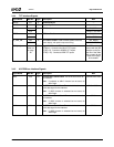
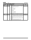
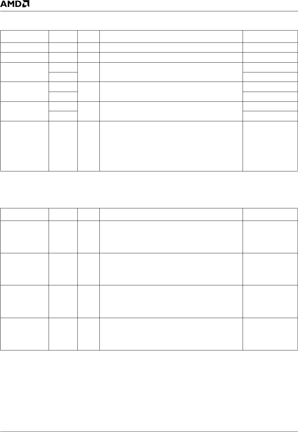
3.4.4 TFT Interface Signals
Signal Name Ball No. Type Description Mux
HSYNC A11 O Horizontal Sync ---
VSYNC B11 O Vertical Sync ---
TFTDCK AA1 O TFT Clock. IDE_RST#
A10 GPIO17+ IOCS0#
TFTDE P2 O TFT Data Enable. IDE_CS1#
B18 ACK#+FPCICLK
FP_VDD_ON AB1 O TFT Power Control. Used to enable power to the flat
panel display, with power sequence timing.
IDE_DATA4
V30 GXCLK+TEST3
TFTD[17:0] See
Table 3-3
on page
40.
O Digital RGB Data to TFT.
TFTD[5:0] - Connect to the BLUE TFT inputs.
TFTD[11:6] - Connect to GREEN TFT inputs.
TFTD[17:12] - Connect to RED TFT inputs.
The TFT interface is
muxed with the IDE
interface or the Par-
allel Port. See Table
3-5 on page 45 and
Table 3-6 on page
46 for details.
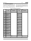
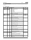
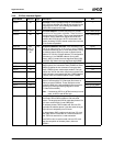
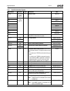
3.4.5 ACCESS.bus Interface Signals
Signal Name Ball No. Type Description Mux
AB1C N31 I/O ACCESS.bus 1 Serial Clock. This is the serial clock for
the interface.
Note: If selected as AB1C function but not used, tie
AB1C high.
GPIO20+DOCCS#
AB1D N30 I/O ACCESS.bus 1 Serial Data. This is the bidirectional
serial data signal for the interface.
Note: If AB1D function is selected but not used, tie
AB1D high.
GPIO1+IOCS1#
AB2C N29 I/O ACCESS.bus 2 Serial Clock. This is the serial clock for
the interface.
Note: If AB2C function is selected but not used, tie
AB2C high.
GPIO12
AB2D M29 I/O ACCESS.bus 2 Serial Data. This is the bidirectional
serial data signal for the interface.
Note: If AB2D function is selected but not used, tie
AB2D high.
GPIO13