338 AMD Geode™ SC3200 Processor Data Book
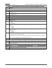
Video Processor Module - Video Processor Registers - Function 4
32581C
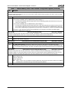
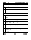
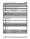
Offset 4Ch-4Fh Video De-Interlacing and Alpha Control Register (R/W) Reset Value: 00060000h
31:22 Reserved.
21:20 ALPHA3_WIN_PRIORITY (Alpha Window 3 Priority). Determines the priority of Alpha Window 3. A higher number indi-
cates a higher priority. Priority is used to determine display order for overlapping alpha windows.
00: Lowest priority (default).
01: Medium priority.
10: Highest priority.
11: Illegal.
Note: Priority of enabled alpha windows must be different.
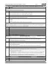
19:18 ALPHA2_WIN_PRIORITY (Alpha Window 2 Priority). Determines the priority of Alpha Window 2. A higher number indi-
cates a higher priority. Priority is used to determine display order for overlapping alpha windows.
00: Lowest priority (default).
01: Medium priority.
10: Highest priority.
11: Illegal.
Note: Priority of enabled alpha windows must be different.
17:16 ALPHA1_WIN_PRIORITY (Alpha Window 1 Priority). Determines the priority of Alpha Window 1. A higher number indi-
cates a higher priority. Priority is used to determine display order for overlapping alpha windows.
00: Lowest priority (default).
01: Medium priority.
10: Highest priority.
11: Illegal.
Note: Priority of enabled alpha windows must be different.
15:14 Reserved
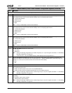
13 GV_SEL (GV Select). Selects input video format.
0: YUV format.
1: RGB format.
Note: Mixing and blending configurations are created using bits [13, 11:9] of this register. See Table 7-1 "Valid Mixing/
Blending Configurations" on page 321.
If this bit is set to 1, EN_42X (F4BAR0+Memory Offset 00h[28]) must be programmed to 0.
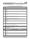
12 VID_LIN_INV (Video Line Invert). When this bit is set, it allows the video window to be positioned at odd offsets with
respect to the first line. The values below are recommended if VID_Y_START (F4BAR0+Memory Offset 0Ch[10:0]) is an
odd (set to 1) or even (set to 0) number of lines from the start of the active display.
0: Even.
1: Odd.
11 Reserved: Set to 0.
10 CSC_FOR_VIDEO (Color Space Converter for Video). Determines whether or not the video stream from the video mod-
ule is passed through the CSC.
0: Disable. The video stream is sent "as is" to the video Mixer/Blender.
1: Enable. The video stream is passed through the CSC (for YUV to RGB conversion).
Note: Mixing and blending configurations are created using bits [13,11:9] of this register. See Table 7-1 "Valid Mixing/
Blending Configurations" on page 321.
9 VIDEO_BLEND_MODE (Video Blending Mode). Allows selection of the type of video (i.e., interlaced or progressive) used
for blending.
0: Progressive video used for blending.
1: Interlaced video used for blending.
Note: Mixing and blending configurations are created using bits [13,11:9] of this register. See Table 7-1 "Valid Mixing/
Blending Configurations" on page 321.
Table 7-7. F4BAR0+Memory Offset: Video Processor Configuration Registers (Continued)
Bit Description


