


AMD Geode™ SC3200 Processor Data Book 355
Electrical Specifications
32581C
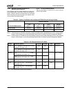
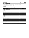
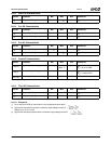
9.1.6 Ball Capacitance and Inductance
Table 9-8 gives ball capacitance and inductance values.
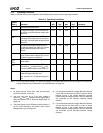
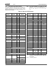
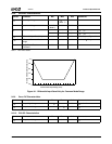
Table 9-7. DC Characteristics for Active Idle, Sleep, and Off States
Symbol ParameterNote 1 Min Typ Max Unit Comments
I
CC3IDLE
f
CLK
= 233 MHz, I/O Current @ V
IO
= 3.3V
(Nominal); CPU state = Active Idle
260 mA I
CC
for V
IO
f
CLK
= 266 MHz, I/O Current @ V
IO
= 3.3V
(Nominal); CPU state = Active Idle
270
I
CC3SLP
I/O Current @ V
IO
= 3.3V (Nominal);
CPU state = Sleep
20 30 mA I
CC
for V
IO
,
Note 2
I
COREIDLE
f
CLK
= 233 MHz, Core Current @ V
CORE
=
1.8V (Nominal); CPU state = Active Idle
360 mA I
CC
for V
CORE
f
CLK
= 266 MHz, Core Current @ V
CORE
=
1.8V (Nominal); CPU state = Active Idle
380
I
CORESLP
Core Current @ V
CORE
= 1.8V (Nominal);
CPU state = Sleep
20 30 mA I
CC
for V
CORE
,
Note 2
I
SBOFF
SB Current @ V
SB
= 3.3V (Nominal);
CPU state = Off
<1 mA
I
SBLOFF
SBL Current @ V
SBL
= 1.8V (Nominal);
CPU state = Off
<1 mA I
CC
for V
SBL
,
Note 3
I
BAT
BAT Current @ V
BAT
= 3.0 (Nominal);
CPU state = Off
750µA
Note 1. f
CLK
ratings refer to internal clock frequency.
Note 2. All inputs are at 0.2V or V
IO
– 0.2 (CMOS levels). All inputs are held static, and all outputs are unloaded (static I
OUT
= 0 mA).
Note 3. All V
SBL
supplied inputs are at 0.2V or V
SBL
– 0.2 (CMOS levels). All inputs are held static, and all outputs are un-
loaded (static I
OUT
= 0 mA).
Table 9-8. Ball Capacitance and Inductance
Symbol Parameter Min Typ Max Unit Comments
C
IN
Input Pin Capacitance 4 7 pF Note 1
C
IN
Clock Input Capacitance 5 8 12 pF Note 1
C
IO
I/O Pin Capacitance 10 12 pF Note 1
C
O
Output Pin Capacitance 6 8 pF Note 1
L
PIN
Pin Inductance 20 nH Note 2
Note 1. T
A
= 25°C, f = 1 MHz. All capacitances are not 100% tested.
Note 2. Not 100% tested.