


60 AMD Geode™ SC3200 Processor Data Book
Signal Definitions
32581C
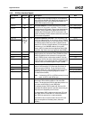
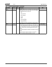
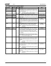
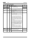
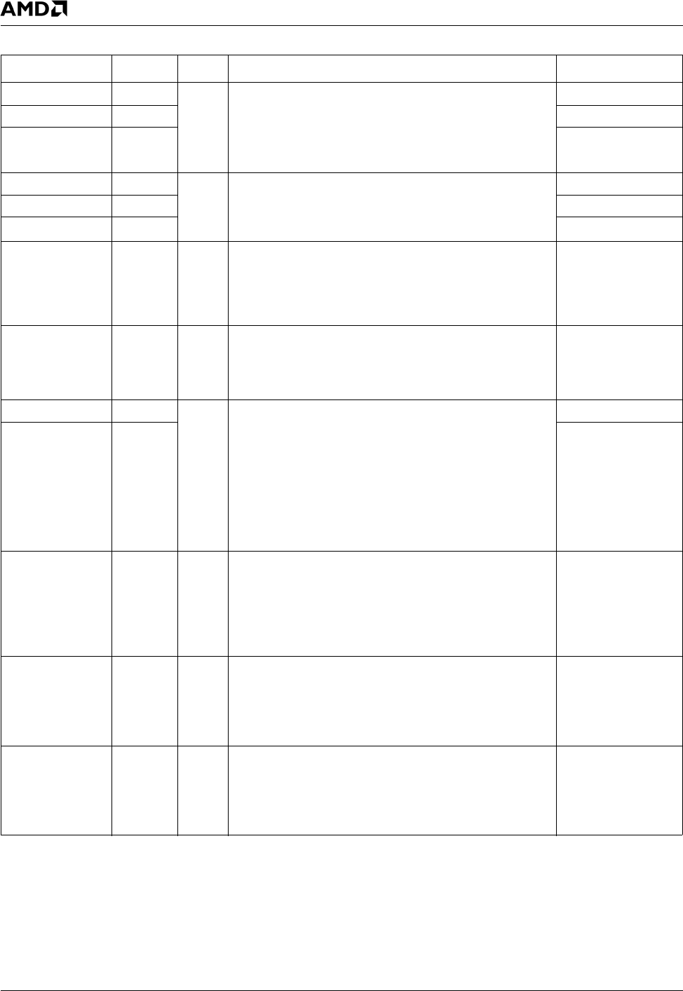
3.4.11 Serial Ports (UARTs) Interface Signals
Signal Name Ball No. Type Description Mux
SIN1 AG2 I Serial Inputs. Receive composite serial data from the
communications link (peripheral device, modem or other
data transfer device).
Note: If selected as SIN2 or SIN3 function(s) but not
used, then signal(s) should be tied high.
---
SIN2 E28 SDTEST3
SIN3 AK8 IRRX1
SOUT1 AF3 O Serial Outputs. Send composite serial data to the com-
munications link (peripheral device, modem or other data
transfer device). These signals are set active high after a
system reset.
CLKSEL1 (Strap)
SOUT2 D29 CLKSEL2 (Strap)
SOUT3 C11 IRTX
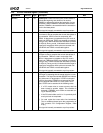
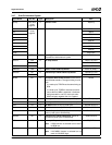
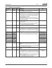
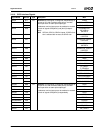
RTS2# C30 O Request to Send. When low, indicates to the modem or
other data transfer device that the corresponding UART
is ready to exchange data. A system reset sets these sig-
nals to inactive high, and loopback operation holds them
inactive.
GPIO7+
IDE_DACK1#
CTS2# C31 I Clear to Send. When low, indicates that the modem or
other data transfer device is ready to exchange data.
Note: If selected as CTS2# function but not used, tie
CTS2# low.
GPIO8+
IDE_DREQ1
DTR1#/BOUT1 AG1 O Data Terminal Ready Outputs. When low, indicate to
the modem or other data transfer device that the UART is
ready to establish a communications link. After a system
reset, these balls provide the DTR# function and set
these signals to inactive high. Loopback operation drive
them inactive.
Baud Outputs. Provide the associated serial channel
baud rate generator output signal if test mode is selected
(i.e., bit 7 of the EXCR1 Register is set).
GPIO18
DTR2#/BOUT2 D28 GPIO6+IDE_IOR1#
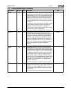
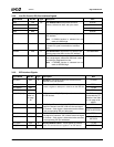
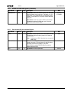
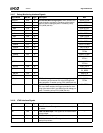
RI2# AJ8 I Ring Indicator. When low, indicates to the modem that a
telephone ring signal has been received by the modem.
They are monitored during power-off for wakeup event
detection.
Note: If selected as RI2# function but not used, tie
RI2# high.
GPIO11+IRQ15
DCD2# C28 I Data Carrier Detected. When low, indicates that the
data transfer device (e.g., modem) is ready to establish a
communications link.
Note: If selected as DCD2# function but not used, tie
DCD2# high.
GPIO9+IDE_IOW1#
+SDTEST2
DSR2# B29 I Data Set Ready. When low, indicates that the data trans-
fer device (e.g., modem) is ready to establish a communi-
cations link.
Note: If selected as DSR2# function but not used, tie
DSR2# low.
GPIO10+
IDE_IORDY1