


AMD Geode™ SC3200 Processor Data Book 55
Signal Definitions
32581C
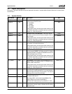
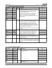
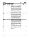
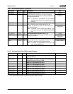
LOCK# H3 I/O Lock Operation. LOCK# indicates an atomic operation
that may require multiple transactions to complete. When
LOCK# is asserted, non-exclusive transactions may pro-
ceed to an address that is not currently locked (at least
16 bytes must be locked). A grant to start a transaction
on PCI does not guarantee control of LOCK#. Control of
LOCK# is obtained under its own protocol in conjunction
with GNT#.
It is possible for different agents to use PCI while a single
master retains ownership of LOCK#. The arbiter can
implement a complete system lock. In this mode, if
LOCK# is active, no other master can gain access to the
system until the LOCK# is de-asserted.
This signal is internally connected to a pull-up resistor.
---
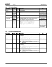
DEVSEL# E4 I/O Device Select. DEVSEL# indicates that the driving
device has decoded its address as the target of the cur-
rent access. As an input, DEVSEL# indicates whether
any device on the bus has been selected. DEVSEL# is
also driven by any agent that has the ability to accept
cycles on a subtractive decode basis. As a master, if no
DEVSEL# is detected within and up to the subtractive
decode clock, a master abort cycle is initiated (except for
special cycles which do not expect a DEVSEL#
returned).
This signal is internally connected to a pull-up resistor.
BHE#
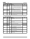
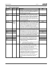
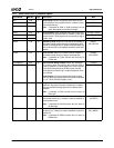
PERR# H2 I/O Parity Error. PERR# is used for reporting data parity
errors during all PCI transactions except a Special Cycle.
The PERR# line is driven two PCI clocks after the data in
which the error was detected. This is one PCI clock after
the PAR that is attached to the data. The minimum dura-
tion of PERR# is one PCI clock for each data phase in
which a data parity error is detected. PERR# must be
driven high for one PCI clock before being placed in TRI-
STATE. A target asserts PERR# on write cycles if it has
claimed the cycle with DEVSEL#. The master asserts
PERR# on read cycles.
This signal is internally connected to a pull-up resistor.
---
SERR# H1 I/O System Error. SERR# can be asserted by any agent for
reporting errors other than PCI parity. When the PFS bit
is enabled in the GX1 module’s PCI Control Function 2
register (Index 41h[5]), SERR# is asserted upon asser-
tion of PERR#.
This signal is internally connected to a pull-up resistor.
---
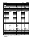
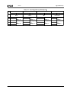
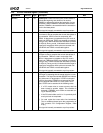
3.4.6 PCI Bus Interface Signals (Continued)
Signal Name BalL No. Type Description Mux