


314 AMD Geode™ SC3200 Processor Data Book
Video Processor Module
32581C
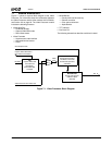
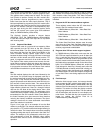
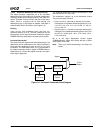
The GenLock control hardware is used to synchronize the
video input’s field with the GX1 module’s graphics frame.
The graphics data is always sent full frame. For the Gen-
Lock function to perform correctly, the GX1 module’s Dis-
play Controller must be programmed to have a slightly
faster frame time then the video input’s field time. This is
best accomplished by programming the GX1 module’s Dis-
play Controller with a few less (three to five) horizontal lines
then the VIP interface. GenLock is accomplished by stop-
ping the clock driving the GX1 module’s graphics frame
until the VIP vertical sync occurs (plus some additional
delay, via F4BAR0+Memory Offset 424h).
The GenLock function provides a timeout feature
(GENLOCK_TOUT_EN, F4BAR0+Memory Offset 420h[4])
in case the video port input clock stops due to a problem
with incoming video.
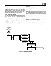
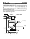
7.2.1.2 Capture Video Mode
Capture Video mode is a process for bus mastering Video
data received from the VIP block to the GX1 module’s
Video Frame Buffer. The GX1 module’s Display Controller
then moves the data from the Video Frame Buffer to the
Video Formatter. Usually Capture Video mode is used
because the data coming in from the VIP block is interlaced
and has a 30 Hz refresh rate (NTSC format) and the TFT
panel, is progressive and has a 60 to 85 Hz refresh rate.
The Capture Video mode process must convert the inter-
laced data to progressive data and change the frames per
second. There are two methods to perform the interlaced
to progressive conversion; Bob and Weave. Each method
uses a different mechanism to up the refresh rate
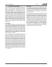
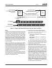
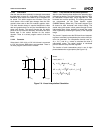
Bob
The Bob method displays the odd frame followed by the
even frame. If a full-scale image is displayed, each line in
the odd and even field must be vertically doubled (see Sec-
tion 7.2.2.5 "2-Tap Vertical and Horizontal Upscalers" on
page 319) because each odd and each even field only con-
tain one-half a frames worth of data. This means that the
Bob method reduces the video image resolution, but has a
higher effective refresh rate. If there is a change of refresh
rate from the VIP block to the display device, then a field
will sometimes be displayed twice. The advantage of this
method is that the process is simple as only half the data is
transmitted from the GX1 module’s Video Frame Buffer to
the Video Processor per a given amount of time, therefore
reducing the memory bandwidth requirement. The disad-
vantage is that there are some observable visual effects
due to the reduction in resolution.
Figure 7-5 on page 315 is an example of how the Bob
method is performed. The example assumes that the dis-
play device is a TFT at 85 Hz refresh and single buffering is
used for the data. The example does not assume anything
regarding scaling that may be performed in the Video Pro-
cessor. The example is only presented to allow for a gen-
eral understanding of how the SC3200’s video support
hardware works and not as an all-inclusive statement of
operation.
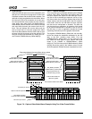
The following procedure is an example of how to create a
Bob method. This example assumes single buffering in the
GX1 module’s video frame buffer. The Video Processor
registers that control the VIP bus master only need to be
initialized.
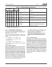
1) Program the VIP bus master address registers.
Three registers control where the VIP video data is
stored in the GX1 module’s frame buffer:
– F4BAR2+Memory Offset 20h – Video Data Odd
Base Address
– F4BAR2+Memory Offset 24h – Video Data Even
Base Address
– F4BAR2+Memory Offset 28h – Video Data Pitch
The Video Data Even Base Address must be sepa-
rated from the Video Data Odd Base Address by at
least the field data size. The Video Data Pitch register
must be programmed to 00000000h.
2) Program other VIP bus master support registers.
In F4BAR2+Memory Offset 00h, make sure that the
VIP FIFO bus request threshold is set to 32 bytes (bit
22 = 1) and that the Video Input Port mode is set to
CCIR-656. An interrupt needs to be generated so that
the GX1 module’s video frame buffer pointer can flip to
the field that has completed transfer to the video frame
buffer. So in F4BAR2+Memory Offset 04h, enable the
Field Interrupt bit. Auto-Flip is normally set to allow the
CCIR-656 Decoder to identify which field is being pro-
cessed. Capture video data needs to be enabled and
Run Mode Capture is set to Start Capture at beginning
of next field. Data is now being captured to the frame
buffer.
3) Field Interrupt.
When the field interrupt occurs, the interrupt handler
must program the GX1 module’s video buffer start off-
set value (GX_BASE+Memory Offset 8320h) with the
address of the field that was just received from the VIP
interface. This action will cause the display controller
to ping-pong between the two fields. The new address
will not take affect until the start of a new display con-
troller frame. The field that was just received can be
known by reading the Current Field bit at
F4BAR2+Memory Offset 08h[24].