


198 AMD Geode™ SC3200 Processor Data Book
Core Logic Module - Bridge, GPIO, and LPC Registers - Function 0
32581C
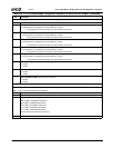
Index 60h-63h ACPI Control Register (R/W) Reset Value: 00000000h
31:8 Reserved. Must be set to 0.
7 SUSP_3V Shut Down PLL5. Allow internal SUSP_3V to shut down PLL5.
0: Clock generator is stopped when internal SUSP_3V is active.
1: Clock generator continues working when internal SUSP_3V is active.
6 SUSP_3V Shut Down PLL4. Allow internal SUSP_3V to shut down PLL4
0: Clock generator is stopped when internal SUSP_3V is active.
1: Clock generator continues working when internal SUSP_3V is active.
5 SUSP_3V Shut Down PLL3. Allow internal SUSP_3V to shut down PLL3.
0: Clock generator is stopped when internal SUSP_3V is active.
1: Clock generator continues working when internal SUSP_3V is active.
4 SUSP_3V Shut Down PLL2. Allow internal SUSP_3V to shut down PLL2.
0: Clock generator is stopped when internal SUSP_3V is active.
1: Clock generator continues working when internal SUSP_3V is active.
3 SUSP_3V Shut Down PLL6. Allow internal SUSP_3V to shut down PLL6.
0: Clock generator is stopped when internal SUSP_3V is active.
1: Clock generator continues working when internal SUSP_3V is active.
2 ACPI C3 SUSP_3V Enable. Allow internal SUSP_3V to be active during C3 state.
0: Disable.
1: Enable.
1 ACPI SL1 SUSP_3V Enable. Allow internal SUSP_3V to be active during SL1 sleep state.
0: Disable.
1: Enable.
0 ACPI C3 Support Enable. Allow support of C3 states.
0: Disable.
1: Enable.
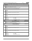
Index 64h-6Bh Reserved Reset Value: 00h
Index 6Ch-6Fh ROM Mask Register (R/W) Reset Value: 0000FFF0h
Note: Register must be read/written as a DWORD.
31:16 Reserved. Must be written to 0.
15:8 Reserved. Must be written to FFh.
7:4 ROM Size. If F0 Index 52h[2] = 1:
0000: 16 MB = FF000000h-FFFFFFFFh
1000: 8 MB = FF800000h-FFFFFFFFh
1100: 4 MB = FFC00000h-FFFFFFFFh
1110: 2 MB = FFE00000h-FFFFFFFFh
1111: 1 MB = FFF00000h-FFFFFFFFh
All other settings for these bits are reserved.
3:0 Reserved. Must be set to 0.
Table 6-29. F0: PCI Header/Bridge Configuration Registers for GPIO and LPC Support (Continued)
Bit Description