


252 AMD Geode™ SC3200 Processor Data Book
Core Logic Module - SMI Status and ACPI Registers - Function 1
32581C
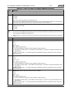
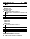
Offset 14h GPWIO Control Register 1 (R/W) Reset Value: 00h
7:4 Reserved. Must be set to 0.
3 Reserved.
2 GPWIO2_POL. Select GPWIO2 polarity.
0: Active high
1: Active low
1 GPWIO1_POL. Select GPWIO1 polarity.
0: Active high
1: Active low
0 GPWIO0_POL. Select GPWIO0 polarity.
0: Active high
1: Active low
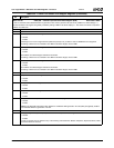
Offset 15h GPWIO Control Register 2 (R/W) Reset Value: 00h
7 Reserved.
6 GPWIO_SMIEN2. Allow GPWIO2 to generate an SMI.
0: Disable. (Default)
1: Enable.
A fixed high-to-low or low-to-high transition (debounce period) of 31 µs exists in order for GPWIO2 to be recognized.
Bit 2 of this register must be set to 0 (input) for GPWIO2 to be able to generate an SMI.
If asserted, this bit overrides the setting of F1BAR1+I/O Offset 12h[10] and its status is reported in F1BAR0+I/O Offset 00h/
02h[0].
5 GPWIO_SMIEN1. Allow GPWIO1 to generate an SMI.
0: Disable. (Default)
1: Enable.
See F1BAR1+I/O Offset 07h[3] for debounce information.
Bit 1 of this register must be set to 0 (input) for GPWIO1 to be able to generate an SMI.
If asserted, this bit overrides the setting of F1BAR1+I/O Offset 12h[9] and its status is reported in F1BAR0+I/O Offset 00h/
02h[0].
4 GPWIO_SMIEN0. Allow GPWIO0 to generate an SMI.
0: Disable. (Default)
1: Enable.
See F1BAR1+I/O Offset 07h[3] for debounce information.
Bit 0 of this register must be set to 0 (input) for GPWIO0 to be able to generate an SMI.
If enabled, this bit overrides the setting of F1BAR1+I/O Offset 12h[8] and its status is reported in F1BAR0+I/O Offset 00h/
02h[0].
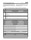
3 Reserved.
2 GPWIO2_DIR. Selects the direction of GPWIO2.
0: Input.
1: Output.
1 GPWIO1_DIR. Selects the direction of GPWIO1.
0: Input.
1: Output.
0 GPWIO0_DIR. Selects the direction of the GPWIO0.
0: Input.
1: Output.
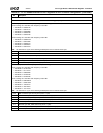
Table 6-34. F1BAR1+I/O Offset: ACPI Support Registers (Continued)
Bit Description