Alpha 21264/EV67 Hardware Reference Manual
xiii
Tables
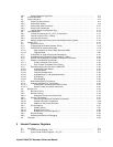
1–1 Integer Data Types . . . . . . . . . . . . . . . . . . . . . . . . . . . . . . . . . . . . . . . . . . . . . . . . . . . . . . . . 1–2
2–1 Pipeline Abort Delay (GCLK Cycles). . . . . . . . . . . . . . . . . . . . . . . . . . . . . . . . . . . . . . . . . . . 2–16
2–2 Instruction Name, Pipeline, and Types . . . . . . . . . . . . . . . . . . . . . . . . . . . . . . . . . . . . . . . . . 2–17
2–3 Instruction Group Definitions and Pipeline Unit. . . . . . . . . . . . . . . . . . . . . . . . . . . . . . . . . . . 2–18
2–4 Instruction Class Latency in Cycles. . . . . . . . . . . . . . . . . . . . . . . . . . . . . . . . . . . . . . . . . . . . 2–20
2–5 Minimum Retire Latencies for Instruction Classes . . . . . . . . . . . . . . . . . . . . . . . . . . . . . . . . 2–21
2–6 Instructions Retired Without Execution . . . . . . . . . . . . . . . . . . . . . . . . . . . . . . . . . . . . . . . . . 2–23
2–7 Rules for I/O Address Space Load Instruction Data Merging . . . . . . . . . . . . . . . . . . . . . . . . 2–28
2–8 Rules for I/O Address Space Store Instruction Data Merging. . . . . . . . . . . . . . . . . . . . . . . . 2–29
2–9 MAF Merging Rules. . . . . . . . . . . . . . . . . . . . . . . . . . . . . . . . . . . . . . . . . . . . . . . . . . . . . . . . 2–30
2–10 Memory Reference Ordering. . . . . . . . . . . . . . . . . . . . . . . . . . . . . . . . . . . . . . . . . . . . . . . . . 2–31
2–11 I/O Reference Ordering. . . . . . . . . . . . . . . . . . . . . . . . . . . . . . . . . . . . . . . . . . . . . . . . . . . . . 2–31
2–12 TB Fill Flow Example Sequence 1 . . . . . . . . . . . . . . . . . . . . . . . . . . . . . . . . . . . . . . . . . . . . 2–34
2–13 TB Fill Flow Example Sequence 2 . . . . . . . . . . . . . . . . . . . . . . . . . . . . . . . . . . . . . . . . . . . . 2–35
2–14 Floating-Point Control Register Fields. . . . . . . . . . . . . . . . . . . . . . . . . . . . . . . . . . . . . . . . . . 2–36
2–15 21264/EV67 AMASK Values. . . . . . . . . . . . . . . . . . . . . . . . . . . . . . . . . . . . . . . . . . . . . . . . . 2–38
2–16 AMASK Bit Assignments. . . . . . . . . . . . . . . . . . . . . . . . . . . . . . . . . . . . . . . . . . . . . . . . . . . . 2–38
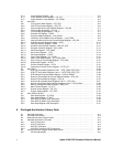
3–1 Signal Pin Types Definitions . . . . . . . . . . . . . . . . . . . . . . . . . . . . . . . . . . . . . . . . . . . . . . . . . 3–3
3–2 21264/EV67 Signal Descriptions. . . . . . . . . . . . . . . . . . . . . . . . . . . . . . . . . . . . . . . . . . . . . . 3–3
3–3 21264/EV67 Signal Descriptions by Function . . . . . . . . . . . . . . . . . . . . . . . . . . . . . . . . . . . . 3–6
3–4 Pin List Sorted by Signal Name. . . . . . . . . . . . . . . . . . . . . . . . . . . . . . . . . . . . . . . . . . . . . . . 3–8
3–5 Pin List Sorted by PGA Location. . . . . . . . . . . . . . . . . . . . . . . . . . . . . . . . . . . . . . . . . . . . . . 3–12
3–6 Ground and Power (VSS and VDD) Pin List . . . . . . . . . . . . . . . . . . . . . . . . . . . . . . . . . . . . 3–16
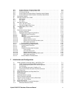
4–1 Translation of Internal References to External Interface Reference . . . . . . . . . . . . . . . . . . . 4–5
4–2 21264/EV67-Supported Cache Block States . . . . . . . . . . . . . . . . . . . . . . . . . . . . . . . . . . . . 4–9
4–3 Cache Block State Transitions . . . . . . . . . . . . . . . . . . . . . . . . . . . . . . . . . . . . . . . . . . . . . . . 4–10
4–4 System Responses to 21264/EV67 Commands . . . . . . . . . . . . . . . . . . . . . . . . . . . . . . . . . . 4–10
4–5 System Responses to 21264/EV67 Commands and 21264/EV67 Reactions. . . . . . . . . . . . 4–11
4–6 System Port Pins. . . . . . . . . . . . . . . . . . . . . . . . . . . . . . . . . . . . . . . . . . . . . . . . . . . . . . . . . . 4–17
4–7 Programming Values for System Interface Clocks . . . . . . . . . . . . . . . . . . . . . . . . . . . . . . . . 4–18
4–8 Program Values for Data-Sample/Drive CSRs . . . . . . . . . . . . . . . . . . . . . . . . . . . . . . . . . . . 4–18
4–9 Forwarded Clocks and Frame Clock Ratio . . . . . . . . . . . . . . . . . . . . . . . . . . . . . . . . . . . . . . 4–19
4–10 Bank Interleave on Cache Block Boundary Mode of Operation . . . . . . . . . . . . . . . . . . . . . . 4–19
4–11 Page Hit Mode of Operation . . . . . . . . . . . . . . . . . . . . . . . . . . . . . . . . . . . . . . . . . . . . . . . . . 4–20
4–12 21264/EV67-to-System Command Fields Definitions . . . . . . . . . . . . . . . . . . . . . . . . . . . . . . 4–20
4–13 Maximum Physical Address for Short Bus Format . . . . . . . . . . . . . . . . . . . . . . . . . . . . . . . . 4–21
4–14 21264/EV67-to-System Commands Descriptions. . . . . . . . . . . . . . . . . . . . . . . . . . . . . . . . . 4–21
4–15 Programming INVAL_TO_DIRTY_ENABLE[1:0]. . . . . . . . . . . . . . . . . . . . . . . . . . . . . . . . . . 4–23
4–16 Programming SET_DIRTY_ENABLE[2:0]. . . . . . . . . . . . . . . . . . . . . . . . . . . . . . . . . . . . . . . 4–24
4–17 21264/EV67 ProbeResponse Command . . . . . . . . . . . . . . . . . . . . . . . . . . . . . . . . . . . . . . . 4–24
4–18 ProbeResponse Fields Descriptions . . . . . . . . . . . . . . . . . . . . . . . . . . . . . . . . . . . . . . . . . . . 4–25
4–19 System-to-21264/EV67 Probe Commands . . . . . . . . . . . . . . . . . . . . . . . . . . . . . . . . . . . . . . 4–26
4–20 System-to-21264/EV67 Probe Commands Fields Descriptions . . . . . . . . . . . . . . . . . . . . . . 4–27
4–21 Data Movement Selection by Probe[4:3]. . . . . . . . . . . . . . . . . . . . . . . . . . . . . . . . . . . . . . . . 4–27
4–22 Next Cache Block State Selection by Probe[2:0] . . . . . . . . . . . . . . . . . . . . . . . . . . . . . . . . . 4–27
4–23 Data Transfer Command Format . . . . . . . . . . . . . . . . . . . . . . . . . . . . . . . . . . . . . . . . . . . . . 4–28
4–24 SysDc[4:0] Field Description . . . . . . . . . . . . . . . . . . . . . . . . . . . . . . . . . . . . . . . . . . . . . . . . . 4–29
4–25 SYSCLK Cycles Between SysAddOut and SysData. . . . . . . . . . . . . . . . . . . . . . . . . . . . . . . 4–32
4–26 Cbox CSR SYSDC_DELAY[4:0] Examples . . . . . . . . . . . . . . . . . . . . . . . . . . . . . . . . . . . . . 4–33
4–27 Four Timing Examples . . . . . . . . . . . . . . . . . . . . . . . . . . . . . . . . . . . . . . . . . . . . . . . . . . . . . 4–34
4–28 Data Wrapping Rules . . . . . . . . . . . . . . . . . . . . . . . . . . . . . . . . . . . . . . . . . . . . . . . . . . . . . . 4–36
4–29 System Wrap and Deliver Data. . . . . . . . . . . . . . . . . . . . . . . . . . . . . . . . . . . . . . . . . . . . . . . 4–37
4–30 Wrap Interleave Order. . . . . . . . . . . . . . . . . . . . . . . . . . . . . . . . . . . . . . . . . . . . . . . . . . . . . . 4–37
4–31 Wrap Order for Double-Pumped Data Transfers. . . . . . . . . . . . . . . . . . . . . . . . . . . . . . . . . . 4–38
4–32 21264/EV67 Commands with NXM Addresses and System Response . . . . . . . . . . . . . . . . 4–39
4–33 21264/EV67 Response to System Probe and In-Flight Command Interaction . . . . . . . . . . . 4–41


