


Alpha 21264/EV67 Hardware Reference Manual
Internal Processor Registers 5–3
Ebox IPRs
5.1 Ebox IPRs
This section describes the internal processor registers that control Ebox functions.
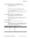
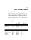
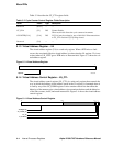
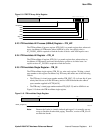
5.1.1 Cycle Counter Register – CC
The cycle counter register (CC) is a read-write register. The lower half of CC is a
counter that, when enabled by way of CC_CTL[32], increments once each CPU cycle.
The upper half of the register is 32 bits of register storage that may be used as a counter
offset as described in the
Alpha Architecture Handbook, Version 4 under Processor Cycle
Counter (PCC) Register.
A HW_MTPR instruction to the CC writes the upper half of the register and leaves the
lower half unchanged. The RPCC instruction returns the full 64-bit value of the register.
Figure 5–1 shows the cycle counter register.
Figure 5–1 Cycle Counter Register
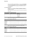
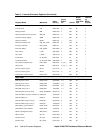
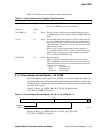
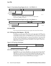
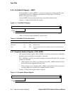
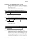
5.1.2 Cycle Counter Control Register – CC_CTL
The cycle counter control register (CC_CTL) is a write-only register through which the
lower half of the CC register may be written and its associated counter enabled and dis-
abled. Figure 5–2 shows the cycle counter control register.
Figure 5–2 Cycle Counter Control Register
Cbox IPRs
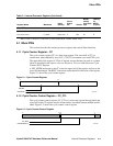
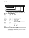
Cbox data C_DATA 0010 1011 6 RW 0L 3
Cbox shift control C_SHFT 0010 1100 6 WO 0L Ò
1
When n equals 1, that process context field is selected (FPE, PPCE, ASTRR, ASTER, ASN).
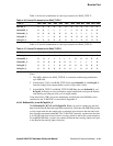
Table 5–1 Internal Processor Registers (Continued)
Register Name Mnemonic
Index
(Binary)
Score-
Board
Bit Access
MT/MF
Issued
from Ebox
Pipe
Latency
for
MFPR
(Cycles)
OFFSET
COUNTER
63 3231 0
LK99-0008A
CC_ENA
COUNTER[31:4]
63 433 33231 0
LK99-0009A