


Alpha 21264/EV67 Hardware Reference Manual
Internal Architecture 2–15
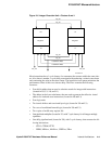
Pipeline Organization
In the slot stage, the branch predictor compares the next Icache index that it generates to
the index that was generated by the line predictor. If there is a mismatch, the branch
predictor wins—the instructions fetched during that cycle are aborted, and the index
predicted by the branch predictor is applied to the Icache during the next cycle. Line
mispredictions result in one pipeline bubble.
The line predictor takes precedence over the branch predictor during memory format
calls or jumps. If the line predictor was trained with a true (as opposed to predicted)
memory format call or jump target, then its contents take precedence over the target
hint field associated with these instructions. This allows dynamic calls or jumps to be
correctly predicted.
The instruction fetcher produces the full VPC address during the fetch stage of the pipe-
line. The Icache produces the tags for both Icache sets 0 and 1 each time it is accessed.
That enables the fetcher to separate set mispredictions from true Icache misses. If the
access was caused by a set misprediction, the instruction fetcher aborts the last two
fetched slots and refetches the slot in the next cycle. It also retrains the appropriate set
prediction bits.
The instruction data is transferred from the Icache to the integer and floating-point reg-
ister map hardware during this stage. When the integer instruction is fetched from the
Icache and slotted into the IQ, the slot logic determines whether the instruction is for
the upper or lower subclusters. The slot logic makes the decision based on the
resources needed by the (up to four) integer instructions in the fetch block. Although all
four instructions need not be issued simultaneously, distributing their resource usage
improves instruction loading across the units. For example, if a fetch block contains
two instructions that can be placed in either cluster followed by two instructions that
must execute in the lower cluster, the slot logic would designate that combination as
EELL and slot them as UULL. Slot combinations are described in Section 2.3.2 and
Table 2–3.
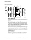
Stage 2 — Map
Instructions are sent from the Icache to the integer and floating-point register maps dur-
ing the slot stage and register renaming is performed during the map stage. Also, each
instruction is assigned a unique 8-bit number, called an inum, which is used to identify
the instruction and its program order with respect to other instructions during the time
that it is in flight. Instructions are considered to be in flight between the time they are
mapped and the time they are retired.
Mapped instructions and their associated inums are placed in the integer and floating-
point queues by the end of the map stage.
Stage 3 — Issue
The 20-entry integer issue queue (IQ) issues instructions at the rate of four per cycle.
The 15-entry floating-point issue queue (FQ) issues floating-point operate instructions,
conditional branch instructions, and store instructions, at the rate of two per cycle. Nor-
mally, instructions are deleted from the IQ or FQ two cycles after they are issued. For
example, if an instruction is issued in cycle n, it remains in the FQ or IQ in cycle n+1
but does not request service, and is deleted in cycle n+2.