


Alpha 21264/EV67 Hardware Reference Manual
Internal Processor Registers 5–25
Mbox IPRs
5.3 Mbox IPRs
This section describes the internal processor registers that control Mbox functions.
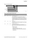
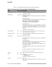
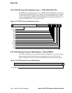
5.3.1 DTB Tag Array Write Registers 0 and 1 – DTB_TAG0, DTB_TAG1
The DTB tag array write registers 0 and 1 (DTB_TAG0 and DTB_TAG1) are write-
only registers through which the two memory pipe DTB tag arrays are written. Write
transactions to DTB_TAG0 and DTB_TAG1 write data to registers outside the DTB
arrays. When write transactions to the corresponding DTB_PTE registers are retired,
the contents of both the DTB_TAG and DTB_PTE registers are written into their
respective DTB arrays, at locations determined by the round-robin allocation algorithm.
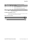
Figure 5–26 shows the DTB tag array write registers 0 and 1.
Figure 5–26 DTB Tag Array Write Registers 0 and 1
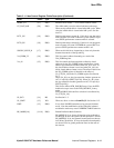
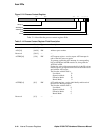
VAL [1] RO Profiled instruction valid.
When set, indicates a nontrapping profiled instruction retired valid.
When clear, indicates that a nontrapping profiled instruction was
killed after the cycle in which it was mapped. Valid retire/abort status
for a trapping profiled instruction is determined by the trap type (see
I_STAT[TRAP_TYPE]).
TAK [0] RO ProfileMe conditional branch taken.
Indicates program branch direction, if the profiled instruction is a
conditional branch.
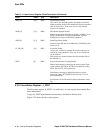
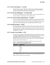
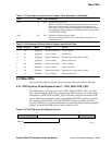
Table 5–16 Performance Counter Control Register Input Select Fields
SL0[4] SL1[3:2] Mode PCTR0 PCTR1
0 00 Aggregate Retired instructions Cycle counting
0 01 Aggregate Cycle counting Not defined
0 10 Aggregate Retired instructions Bcache miss or long latency probes
0 11 Aggregate Cycle counting Mbox replay traps
1 00 ProfileMe Retired instructions Cycle counting
1 01 ProfileMe Cycle counting Inum retire delay
1 10 ProfileMe Retired instructions Bcache miss or long latency probes
1 11 ProfileMe Cycle counting Mbox replay traps
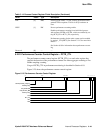
Table 5–15 Performance Counter Control Register Fields Description (Continued)
Name Extent Type Description
63 4847 13 12 0
VA[47:13]
LK
99
-
0035
A