


Alpha 21264/EV67 Hardware Reference Manual
Initialization and Configuration 7–11
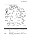
Warm Reset Flow
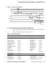
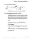
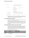
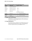
Figure 7–3 Sleep Mode Sequence of Operation
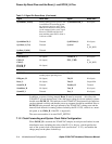
Table 7–7 describes each signal and constraint for the sleep mode sequence.
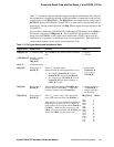
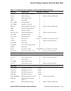
7.4 Warm Reset Flow
The warm reset sequence of operation is triggered by the assertion of the Reset_L sig-
nal line. The reset state machine is initially in RUN state. The 21264/EV67 then, by
default, ramps down the PLL (similar to the sleep flow sequence) and the reset state
machine ends up in the WAIT_RESET state.
Note the effects of entry into that state on the IPRs listed in Table 7–8
.
Table 7–7 Signals and Constraints for the Sleep Mode Sequence
Signal Name Description Constraint
ClkFwdRst_H Signal asserted by the system to
initialize and reset clock forwarding
interfaces
ClkFwdRst_H must be asserted by the system
when entering sleep mode. The system deasserts
ClkFwdRst_H no sooner than one FrameClk_H
cycle after sourcing an interrupt to the 21264/
EV67.
Forwarded clocks Bit clocks forwarded to/from the
21264/EV67
Clocks stop running under ClkFwdRst_H.
System interrupt Asynchronous interrupt which
causes the 21264/EV67 to exit sleep
mode
—
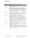
Table 7–8 Effect on IPRs After Warm Reset
IPR Effects After Warm Reset
PAL_BASE Cleared
I_CTL Cleared
PCTX[FPE] Set
WRITE_MANY Cleared (That is, the WRITE_MANY chain is initialized and the Bcache is
turned off.)
state
SLEEP IPR
Wake-up interrupt
SromOE_L
ClkFwdRst_H
internal ClkFwdRst
external Clks
RUN DO
WN1
DOWN2 DOWN3 WAIT_INTR RAMP1 RAMP2
W
AIT_ClkFwdRst0
W
AIT_BiSI
W
AIT_ClkFwdRst1
internal clks
TestStat_H
no min no min
a
c
A
d
e
b
f
FM-06487A.AI4
RUN