Index–6
Alpha 21264/EV67 Hardware Reference Manual
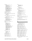
I_CTL Ibox control register, 5–15
after fault reset
, 7–8
after warm reset
, 7–11
at power-on reset state, 7–15
PALshadow registers, 6–11
through sleep mode
, 7–10
VA_48 field update, D–17
I_DA pin type
, 3–3, 9–2
values for
, 9–3
I_DA_CLK pin type
, 3–3, 9–2
values for
, 9–3
I_DC_POWER pin type
, 9–2
I_DC_REF pin type
, 3–3, 9–2
values for
, 9–3
I_STAT Ibox status register
, 5–18
at power-on reset state
, 7–15
IACV fault
, 6–13
Ibox
branch predictor
, 2–3
clear virtual-to-physical map register
CLR_MAP
, 5–21
exception address register EXC_ADDR, 5–8
exception and interrupt logic, 2–8
exception summary register EXC_SUM
, 5–13
floating-point issue queue, 2–7
hardware interrupt clear register HW_INT_CLR,
5–12
Ibox control register I_CTL, 5–15
Ibox process context register PCTX, 5–21
Ibox status register I_STAT
, 5–18
Icache flush ASM register IC_FLUSH_ASM,
5–21
Icache flush register IC_FLUSH
, 5–21
instruction fetch logic, 2–6
instruction virtual address format register
IVA_FORM
, 5–9
instruction-stream translation buffer, 2–5
integer issue queue, 2–6
internal processor registers
, 5–1
interrupt enable and current processor mode
register IER_CM, 5–9
interrupt summary register ISUM
, 5–11
ITB invalidate single register ITB_IS, 5–7
ITB invalidate-all ASM (ASM=0) register
ITB_IAP
, 5–7
ITB invalidate-all register ITB_IA, 5–7
ITB PTE array write register ITB_PTE, 5–6
ITB tag array write register ITB_TAG
, 5–6
PAL base register PAL_BASE, 5–15
performance counter control register
PCTR_CTL
, 5–23
ProfileMe register PMPC, 5–8
register rename maps, 2–6
retire logic
, 2–8
retire logic and mapper, required sequence for,
D–1
sleep mode register SLEEP
, 5–21
software interrupt request register SIRR, 5–10
subsections in, 2–2
virtual program counter logic
, 2–2
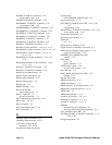
IC_FLUSH Icache flush register
at power-on reset state
, 7–15
IC_FLUSH_ASM Icache flush ASM register
, 5–21
Icache
data errors
, 8–2
error case summary for, 8–9
fill from Bcache error, 8–5
fill from memory error
, 8–7
flush register IC_FLUSH, 5–21
initialized by BiST, 7–12
tag, initialized by BiST
, 7–12
IEEE 1149.1
notes for compliance to
, 11–7
test port reset, 7–16
test port, operation of
, 11–3
IEEE floating-point conformance
, A–14
IEEE floating-point instruction opcodes
, A–9
IER_CM interrupt enable and current processor mode
register
, 5–9
at power-on reset state
, 7–15
IMPLVER instruction values
, 2–38
Independent floating-point function codes
, A–11
INIT_MODE Cbox CSR
, 5–39, 7–12
Initialization mode processing
, 7–12
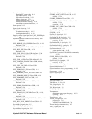
Input dc reference pin. See I_DC_REF pin type
Input differential amplifier clock receiver. See
I_DA_CLK pin type
Input differential amplifier receiver. See I_DA pin
type
Instruction fetch logic
, 2–6
Instruction fetch, issue, and retire unit. See Ibox
Instruction fetch, pipelined
, 2–14
Instruction issue rules
, 2–16
Instruction latencies, pipelined
, 2–20
Instruction ordering
, 2–30
Instruction retire latencies, minimum
, 2–21
Instruction retire rules
F31
, 2–22
floating-point divide, 2–22
floating-point square root, 2–22
pipelined
, 2–21
R31, 2–22
Instruction slot, pipelined
, 2–14
Instruction-stream translation buffer
, 2–5
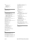
Int_Add_BcClk internal forwarded clock
, 4–44,
4–48
Int_Data_BcClk internal forwarded clock
, 4–44,
4–49
INT_FWD_CLK clock queue
, 4–30
Integer arithmetic trap, pipeline abort delay with
,


