


Intel
®
820E Chipset
R
Design Guide 105
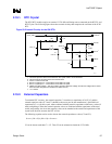
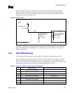
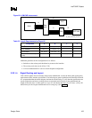
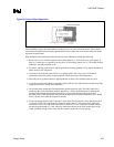
Figure 66. LOM/CNR Interconnect
IO_subsys_LOM-CNR_intercomm
ICH2
Res.
pack
CNR PLC card
B
A
PLC
C D
Table 23. Length Requirements for Figure 66
Configuration A B C D
Intel
®
82562EH 0.5” to 6” 4” to (10” – A)
Intel
®
82562ET 0.5” to 7” 3” to (10” – A)
Dual footprint 0.5” to 6.5” 3.5” to (10” – A)
Intel
®
82562ET/EH card (see
Note)
0.5” to 6.5” 2.5” to (9” – A) 0.5” to 3”
Note: The total trace length should not exceed 13 inches.
Additional guidelines for this configuration are as follows:
• Stubs due to the resistor pack should not be present on the interface.
• The resistor pack value can be 0 Ω or 22 Ω.
• LAN-on-motherboard PLC can have a dual-footprint configuration.
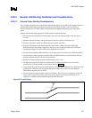
2.22.1.4. Signal Routing and Layout
LAN connect signals must be carefully routed on the motherboard, to meet the timing and signal quality
requirements of this interface specification. The following are general guidelines that should be followed.
It is recommended that the board designer simulate the board routing, to verify that the specifications are
met for flight times and skews resulting from trace mismatch and crosstalk. On the motherboard, the
length of each data trace is either equal to or up to 0.5 inch shorter than the LAN_CLK trace. (LAN_CLK
should always be the longest motherboard trace in each group.) See Figure 67.