


Intel
®
820E Chipset
R
Design Guide 177
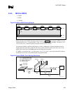
5. System Manufacturing
5.1. Stack-Up Requirement
The Intel 820E chipset platform requires a board stack-up with a 4.5 mil prepreg. This change in
dimension (previously, typically 7 mils) is required because of the signaling environment used for the
Direct RDRAM, AGP 2.0, and hub interface. The RDRAM channel is designed for 28
Ω, and
mismatched impedance will cause signal reflections that will reduce the voltage and timing margins. For
example, with a 2
× clock during 400 MHz operation, which equals a 1.25 ns sampling window, only
100 ps is allotted for the total channel timing error. Channel error results not only from PCB impedance,
but also from PCB and Z
0
process variation. Therefore, it is critical to attain the required 28 Ω
impedance.
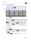
5.1.1. PCB Materials
PCB tolerances determine the Z
0
variation. These tolerances include the trace width, prepreg thickness,
plating thickness, and dielectric constant. The prepreg type affects the H tolerance and
ε
r
, including
single-ply, 2-ply, and resin content.
To design to the correct Z
0
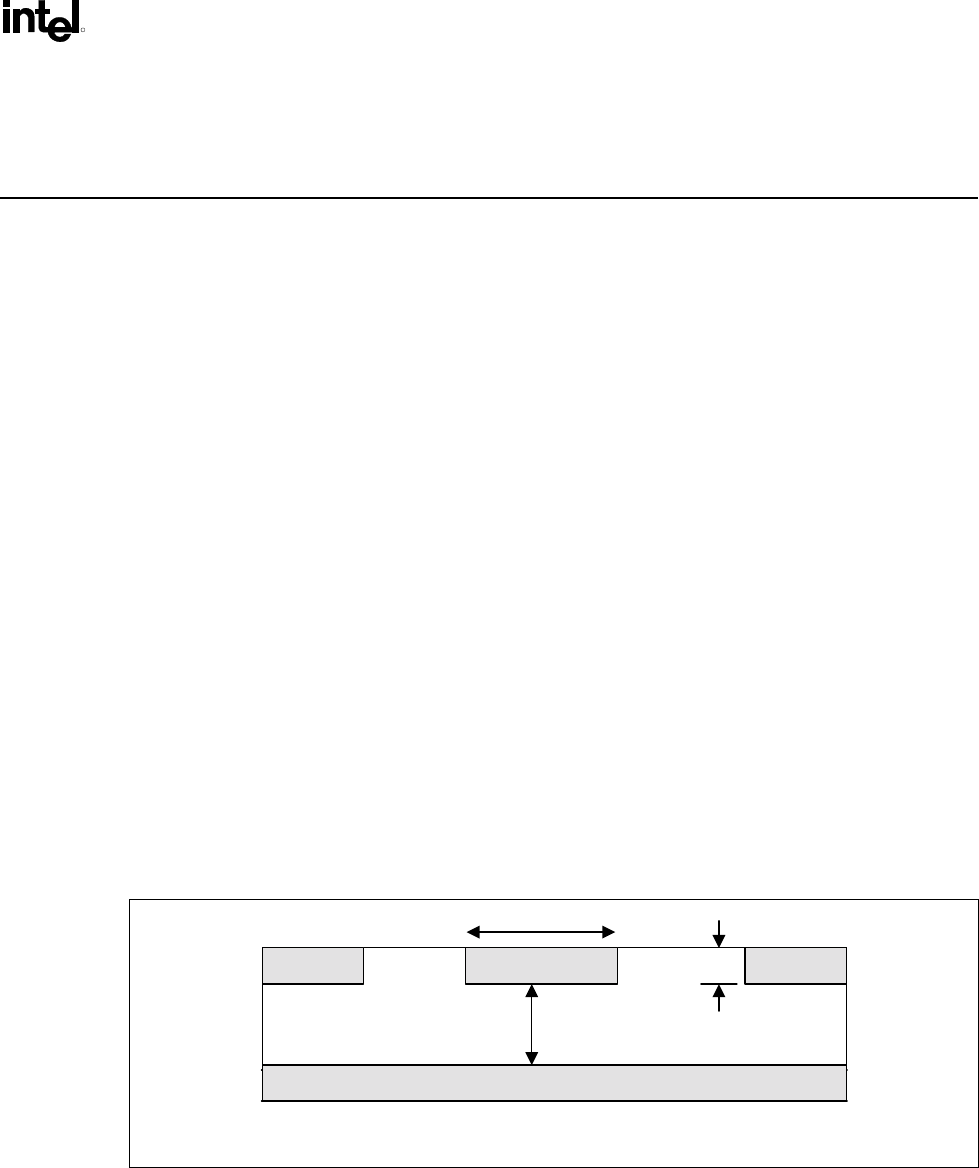
variation, the PCBs typically must meet the following specs (see Table 62):
• Height tolerance: ±10% (~0.4 mil)
• Width tolerance: ±2.5% (~0.4 mil)
• ε
r
tolerance: ±5% (~0.2)
• Stack-up requirement: 28 Ω ± 10%
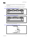
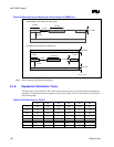
Figure 97. 28 Ω
ΩΩ
Ω Trace Geometry
H
S
T
ε
εε
ε
28_trace_geo