Intel
®
820E Chipset
R
34 Design Guide
Because of the tolerances of components such as PCBs, connectors, and termination resistors, there will
be some reflected voltage on the interconnect. In this multi-symbol interconnect, timings are pattern
dependent because the reflections interfere with the next transfer.
Additionally, coupled noise can greatly affect the performance of high-speed interfaces. Just as in source-
synchronous designs, the odd- and even-mode propagation velocity change creates a skew between the
clock and data or command lines, which reduces the maximum operating frequency of the bus. Efforts
must be made to significantly decrease the crosstalk, as well as the other sources of skew.
To achieve these bus requirements, the Direct RDRAM channel is designed to operate as a transmission
line. All components, including the individual RDRAMs, are incorporated into the design to create a
uniform bus structure that can support up to 33 devices (including the MCH), running at
800 megatransfers/second (MT/s).
2.7.1. Stack-Up
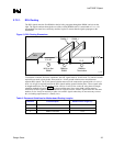
The perfect matching of transmission line impedance and a uniform trace length is essential for the Direct
RDRAM interface to work properly. Maintaining a 28 Ω (± 10%) loaded impedance for every RSL
(Direct RDRAM Signaling Level) signal has changed the requirements for trace width and prepreg
thickness for the Intel 820E chipset platform. (Refer to Section 5.1.)
Achieving a 28 Ω nominal impedance with a traditional 7 mil prepreg requires 28 mil-wide traces. These
traces are too wide to break out of the two rows of RSL balls on the MCH. To reduce the trace width, a
4.5 mil-thick prepreg is required. This thinner prepreg allows 18 mil-wide traces to meet the 28 Ω
(± 10%) nominal impedance requirement. (Refer to Section 5.1, for detailed stack-up requirements.)
2.7.2. Direct RDRAM* Layout Guidelines
The signals on the Direct RDRAM channel are broken into three groups: RSL signals, CMOS signals,
and clocking signals as follows:
• RSL signals
DQA[8:0]
DQB[8:0]
RQ[7:0]
• CMOS signals
CMD (high-speed CMOS signal)
SCK (high-speed CMOS signal)
SIO
• Clocking signals
CTM, CTM#
CFM, CFM#


