


Intel
®
820E Chipset
R
132 Design Guide
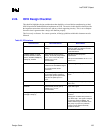
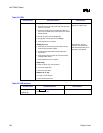
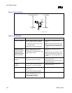
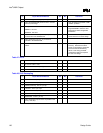
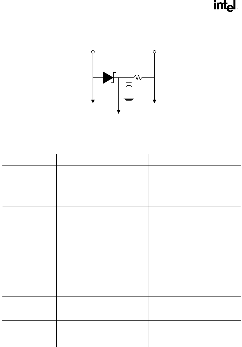
Figure 73. 5V
REF
Circuitry
Vcc supply (3.3 V) 5 V supply
To system To system
Vref
sys_des_5Vref_circ
1 µF
1 k
Ω
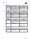
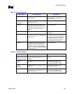
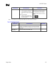
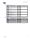
Table 41. IDE Checklist
Checklist Items Recommendations Reason/Effect
PDD[15:0], SDD[15:0] No extra series termination resistors or
other pull-ups/pull-downs are required.
• PDD7/SDD7 doesn’t require a 10 kΩ
pull-down resistor.
Refer to the ATA TAPI-4 specification.
These signals have integrated series
resistors.
NOTE: Simulation data indicates that the
integrated series termination resistors are
a nominal 33
Ω, but can range from 31 Ω
to 43
Ω.
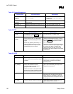
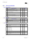
PDIOW#, PDIOR#,
PDDACK#, PDA[2:0],
PDCS1#, PDCS3#,
SDIOW#, SDIOR#,
SDDACK#, SDA[2:0],
SDCS1#, SDCS3#
No extra series termination resistors.
Pads for series resistors can be
implemented if the system designer has
signal integrity concerns.
These signals have integrated series
resistors.
NOTE: Simulation data indicates that the
integrated series termination resistors are
a nominal 33
Ω, but can range from 31 Ω
to 43
Ω.
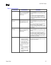
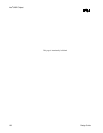
PDREQ
SDREQ
No extra series termination resistors
No pull-down resistors are needed.
These signals have integrated series
resistors in the ICH2.
These signals have integrated pull-down
resistors in the ICH2.
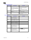
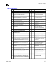
PIORDY
SIORDY
No extra series termination resistors.
Pull-up to 3.3 V via a 4.7 kΩ resistor.
These signals have integrated series
resistors in the ICH2.
IRQ14, IRQ15 Recommend 8.2 kΩ to 10 kΩ pull-up
resistor to 3.3 V.
No extra series termination resistors
Open-drain outputs from drive
IDERST# The PCIRST# signal should be buffered
to form the IDERST# signal. A 33
Ω
series termination resistor is
recommended on this signal.