


Intel
®
820E Chipset
R
Design Guide 125
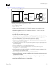
2.24. ICH2 Design Checklist
This checklist highlights design considerations that should be reviewed before manufacturing an Intel
820E chipset-based motherboard that implements an ICH2. The entries in this checklist should provide
the important connections to these devices and any critical supporting circuitry. This is not a complete
list and it doesn’t guarantee that a design will function properly.
This list is only a reference. For correct operation, all design guidelines within this document must be
followed.
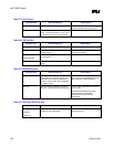
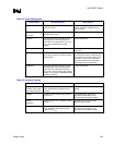
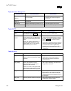
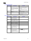
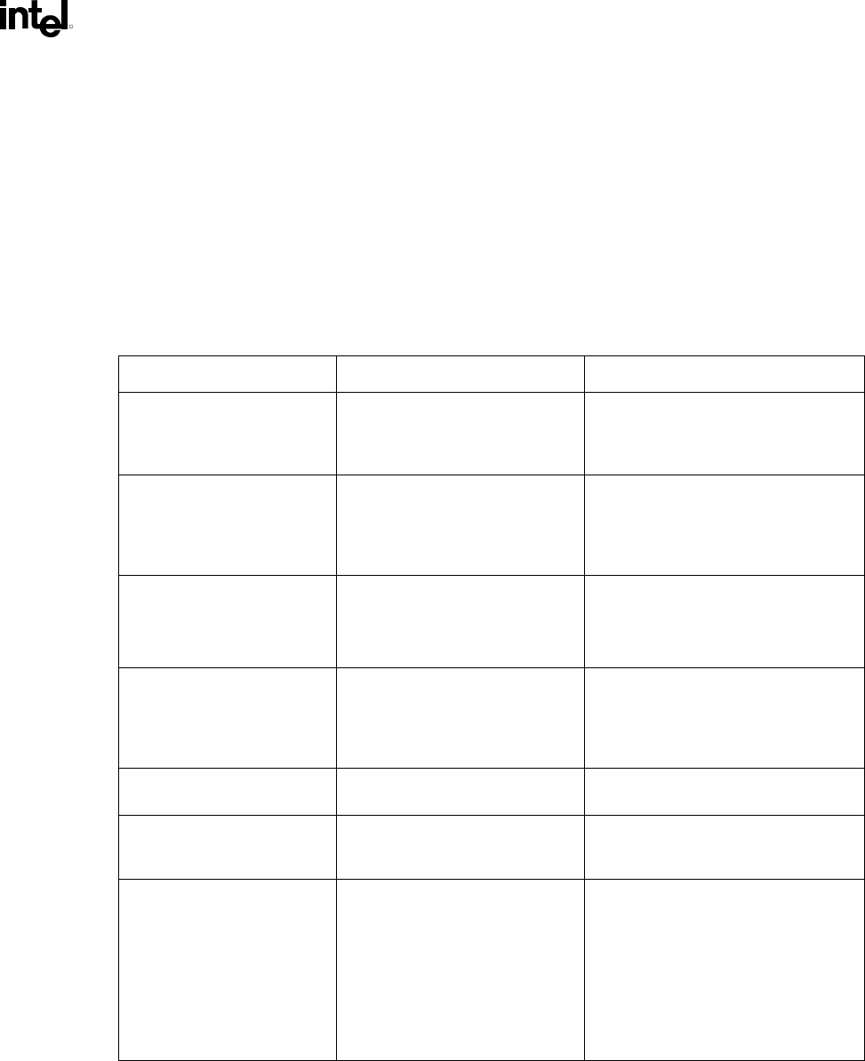
Table 26. PCI Interface
Checklist Items Recommendations Reason/Effect
FYI Inputs to the ICH2 must not be left
floating.
Many GPIO signals are fixed inputs that
must be pulled up to different sources.
See the GPIO section for
recommendations
PERR#, SERR#, PLOCK#,
STOP#, DEVSEL#, TRDY#,
IRDY#, FRAME#, REQ#[4:0],
GPIO[1:0], THRM#
These signals require a pull-up
resistor. An 8.2 k
Ω pull-up resistor
to V
CC
3.3 V or a 2.7 kΩ pull-up
resistor to V
CC
5 V is
recommended.
See the PCI 2.2 Component
Specification.
Pull-up recommendations for V
CC
3.3 V
and V
CC
5 V
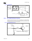
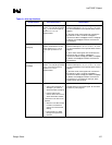
PCIRST# The PCIRST#signal should be
buffered to for the IDERST# signal.
33
Ω series resistor to IDE
connectors
Improves signal integrity
PCIGNT# No external pull-ups are required
on PCI GNT signals. However, if
external pull-ups are implemented,
they must be pulled up to V
CC
3.3 V.
These signals are actively driven by the
ICH2.
PME# No extra pull-up resistors This signal has an integrated pull-up of 9
k
Ω ± 3 kΩ.
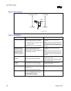
SERIRQ External weak (8.2 kΩ) pull-up
resistor to V
CC
3.3 V is
recommended.
Open-drain signal
GNT[A]# / GPIO[16], GNT[B] /
GNT[5]# / GPIO[17]
No extra pull-up is needed. These signals have integrated pull-ups
of 24 k
Ω.
GNT[A] has an added strap function of
“top block swap.” The signal is sampled
on the rising edge of PWROK. The
default value is high or disabled due to
the pull-up. A jumper to a pull-down
resistor can be added to manually
enable the function.