


Intel
®
820E Chipset
R
Design Guide 83
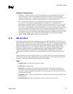
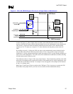
2.12.4. Primary IDE Connector Requirements
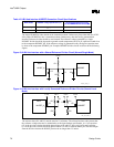
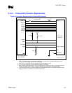
Figure 48. Connection Requirements for Primary IDE Connector
PCIRST# *
PDD[15:0]
PDA[2:0]
PDCS1#
PDCS3#
PDIOR#
PDIOW#
PDDREQ
PIORDY
IRQ14
PDDACK#
GPIOx
ICH2
Primary IDE
Connector
IDE_primary_conn_require
Reset#
PDIAG# / CBLID#
N.C.
Pins 32 & 34
CSEL
* Due to ringing, PCIRST#
must be buffered.
3.3 V
3.3 V
4.7 k
Ω
8.2–10 k
Ω
10 k
Ω
22–47
Ω
PCIRST_BUF#
NOTES:
1. 22 Ω to 47 Ω series resistors are required on RESET#. The correct value should be determined for each
unique motherboard design, based on the signal quality.
2. An 8.2 kΩ to 10 kΩ pull-up resistor is required on IRQ14 and IRQ15 to VCC3.
3. A 4.7 kΩ pull-up resistor to VCC3 is required on PIORDY and SIORDY.
4. Series resistors can be placed on the control and data lines to improve signal quality. The resistors are place
as close as possible to the connector. Values are determined for each unique motherboard design.
5. A 10 kΩ pull-down resistor to ground is required on the PDIAG/CBLID signal. This prevents the GPI pin from
floating if a device is not present on the primary IDE interface.