Intel
®
820E Chipset
R
130 Design Guide
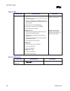
Table 36. System Management
Checklist Items Recommendations Reason/Effect
SMBDATA
SMBCLK
Requires external pull-up resistors to 3.3 V
or 3.3 V standby.
Value of pull-up resistors is determined
by the line load. Open-drain signal in
resume well
SMBALERT#/
GPIO[11]
See GPIO section if SMBALERT# not
implemented.
SMLINK[1:0] Requires external pull-up resistors to 3.3 V. Open-drain signal in resume well
INTRUDER# Pull signal to V
BAT
if not needed. Signal in VCCRTC (V
BAT
) well.
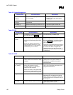
Table 37. RTC
Checklist Items Recommendations Reason/Effect
VBIAS The VBIAS pin of the ICH2 is connected
to a 0.047 µF cap
. See Figure 59
For noise immunity on VBIAS signal
RTCX1
RTCX2
Connect a 32.768 kHz crystal oscillator
across these pins with a 10 M
Ω resistor,
and use 12 pF decoupling caps at each
signal.
RTCX1 may optionally be driven by an
external oscillator instead of a crystal.
These signals are 1.8 V only and must
not be driven by a 3.3 V source.
The ICH2 implements new internal oscillator
circuit as compared with the PIIX4, to reduce
the power consumption. The external circuitry
shown in Figure 59 is required to maintain
RTC accuracy.
The circuitry is required because the new RTC
oscillator is sensitive to step voltage changes
in VCCRTC and VBIAS. A negative step
voltage change of more than 100 mV will
temporarily shut off the oscillator for hundreds
of milliseconds.
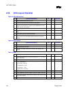
Table 38. AC’97
Checklist Items Recommendations Reason/Effect
AC_SDOUT Requires a jumper to 8.2 kΩ pull-up
resistor. Should not be stuffed for default
operation.
This pin has a weak internal pull-down. To
properly detect a safe_mode condition, a
strong pull-up is required to override this
internal pull-down.
AC_SDIN[1],
AC_SDIN[0]
Requires pads for weak 10 kΩ pull-
downs. Stuff resistor for unused
AC_SDIN signal or AC_SDIN signal
going to the CNR connector.
If there is no codec on the system board,
then both AC_SDIN[1:0] should be pulled
down externally with resistors to ground.
AC_SDIN[1:0] are inputs to an internal OR
gate. If a pin is left floating, the output of the
OR gate will be erroneous.
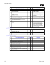
AC_BITCLK No extra pull-down resistors are required. When nothing is connected to the link, the
BIOS must set a shut-off bit for the internal
keeper resistors to be enabled. At that point,
pull-ups/pull-downs are not required on any of
the link signals.
AC_SYNC No extra pull-down resistors are required. Some implementations add termination for
signal integrity. Platform specific.


