


Intel
®
820E Chipset
R
152 Design Guide
3.3. Theory
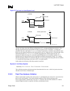
3.3.1. AGTL+
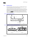
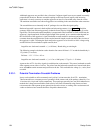
AGTL+ is the electrical bus technology used for the processor bus. This is an incident wave switching,
open-drain bus with external pull-up resistors that provide both the high logic level and termination at
each load. The processor AGTL+ drivers contain a full-cycle active pull-up device to improve system
timings. The AGTL+ specification defines the following:
• Termination voltage (V
TT
)
• Receiver reference voltage (V
REF
) as a function of termination voltage (V
TT
)
• Processor termination resistance (R
TT
)
• Input low voltage (V
IL
)
• Input high voltage (V
IH
)
• NMOS on resistance (RON
N
)
• PMOS on resistance (RON
P
)
• Edge rate specifications
• Ringback specifications
• Overshoot/undershoot specifications.
• Settling limit
3.3.2. Timing Requirements
The system timing for AGTL+ depends on many things. The following elements combine to determine
the maximum and minimum frequencies supportable by the AGTL+ bus:
• Timing range for each agent in the system
Clock to output [T
CO
] (Note that the system load is likely to differ from the “specification”
load, so the T
CO
observed in the system might differ from the T
CO
of the specification.)
Minimum required setup time to clock [T
SU_MIN
] for each receiving agent
• Range of flight time between each component, including
Propagation velocity for the loaded printed circuit board [S
EFF
]
Board loading effect on the effective T
CO
in the system
• Amount of skew and jitter in system clock generation and distribution
• Changes in flight time due to crosstalk, noise, and other effects