Intel
®
820E Chipset
R
134 Design Guide
2.25. ICH2 Layout Checklist
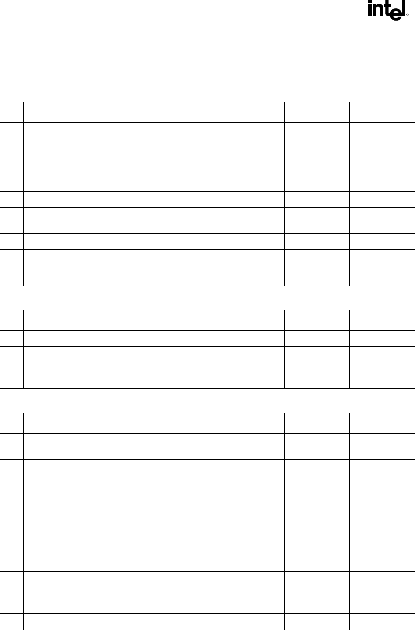
Table 43. 8-Bit Hub Interface
# Layout Recommendations Yes No Comments
1 Board impedance must be 60 Ω ± 10%.
2 Traces must be routed 5 mils wide with 20 mils spacing.
3 In order to break out of the MCH and ICH2 package, the hub interface
signals can be routed 5 on 5. Signals must be separated to 5 on 20
within 300 mils of the package.
4 Max. trace length is 8 inches.
5 Data signals must be matched within ±0.1 inch of the HL_STB diff
pair.
6 Each strobe signal must be the same length.
7 HUBREF divider should be placed no more than 4 inches away from
MCH or ICH2. If so, then separate resistor divider must be placed
locally.
Table 44. IDE Interface
# Layout Recommendations Yes No Comments
1 5 mils wide and 7 mil spaces
2 Max. trace length is 8 inches.
3 Shortest trace length must be 0.5 inch shorter than longest trace
length.
Table 45. USB
# Layout Recommendations Yes No Comments
1 Characteristic impedance of individual signal lines P+, P- : Z
0
= 45 Ω
(90
Ω differential)
2 Stack-up: 9 mils wide, 25 mil spacing between differential pairs
3 Trace characteristics
• Line delay = 160.2 ps
• Capacitance = 3.5 pF
• Inductance = 7.3 nH
• Res at 20
o
C = 53.9 mΩ
4 15 Ω series resistor placed < 1 inch from ICH2.
5 47 pF parallel caps should be placed as close as possible to the ICH2.
6 15 kΩ ± 5% pull-down resistors must be present on the connector side
of the series resistor.
7 Stub length due to 15 kΩ pull-downs should be as short as possible.


