


Intel
®
820E Chipset
R
162 Design Guide
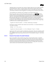
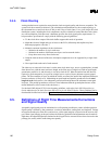
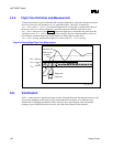
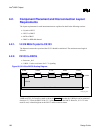
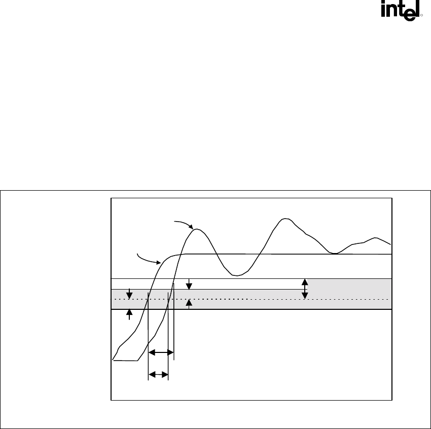
3.5.4. Flight Time Definition and Measurement
Timing measurements consist of minimum and maximum flight times, to take into account the fact that
devices can turn on or off anywhere in a V
REF
guard band region. This region is bounded by
V
REF
– ∆V
REF
and V
REF
+ ∆V
REF
. The minimum flight time for a rising edge is measured from the time
the driver crosses V
REF
when terminated to a test load, to the time when the signal first crosses
V
REF
– ∆V
REF
at the receiver (see Figure 85). Maximum flight time is measured to the point where the
signal first crosses V
REF
+ ∆V
REF
, assuming that the ringback, edge rate, and monotonicity criteria are
met. Similarly, minimum flight time measurements for a falling edge are taken at the
V
REF
+ ∆V
REF
crossing, and maximum flight time is taken at the V
REF
– ∆V
REF
crossing.
Figure 85. Rising-Edge Flight Time Measurement
rising_edge_flight
Overdrive Region
V
REF
Guardband
Driver pin into
test load
Receiver Pin
Tflight-min
Tflight-max
V
REF
+ 200 mV
V
REF
+ 100 mV
V
REF
V
REF
- 100 mV
∆
V
REF
∆
V
REF
3.6. Conclusion
AGTL+ routing requires a significant amount of effort. Planning ahead and allocating the necessary time
for correctly designing a board layout will give the designer the best chance of avoiding the more
difficult task of debugging inconsistent failures caused by poor signal integrity. Intel recommends
planning a layout schedule that allows time for each of the tasks outlined in this document.